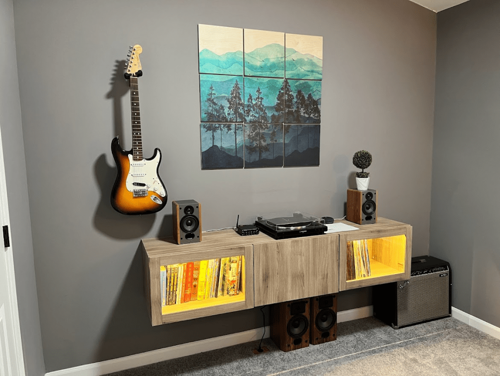
I used to have a record player in my bedroom paired with a couple of old bookshelf speakers and my dad’s beautiful old Pioneer stereo from the ’80s. The record player was also vintage and wasn’t great even back then. I wanted to move my setup to my office, but I also wanted it to look nice and sound even better, so I decided I would upgrade my sound system and install a floating cabinet to organize all my vinyl and books.
I replaced my old record player with an AT-LP60X-BK – an excellent semi-budget turntable with a nice modern look. For the speakers, I purchased a set of Edifier P12s and kept one of the old bookshelf speakers hooked up as a relatively capable subwoofer. The old amplifier is beautiful and powerful, but really needs to be restored to reach it’s full potential – a big project for another time. So, I decided to keep it very simple and went with a mini-amplifier, the Fosi Audio BT30D. The results of my efforts can be seen below – I think it turned out really nice!
It did have one small problem, however. In addition to my turntable, I also had an Amazon Alexa with an audio output that I would use to stream music that I didn’t have on vinyl. The amplifier has Bluetooth, but it didn’t sound quite as good as the Alexa. The amplifier only has a single audio input, so I found myself disconnecting and reconnecting cables quite often. I figured there had to be a better way!
I took a look on Amazon and found a plethora of RCA switches available, but they were either expensive or ugly. So I did what any rational person would do and built my own.
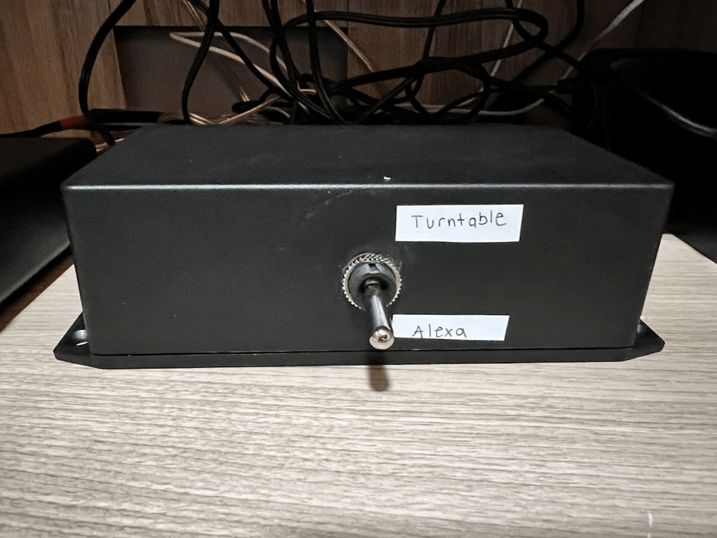
As you can see – it turned out poorly. It also wasn’t particularly cheap. For about $40, I ended up with an ugly, but functional, RCA switcher. I had planned on having it visible, but after seeing the final product, I hid it away inside the cabinet and called it a day.
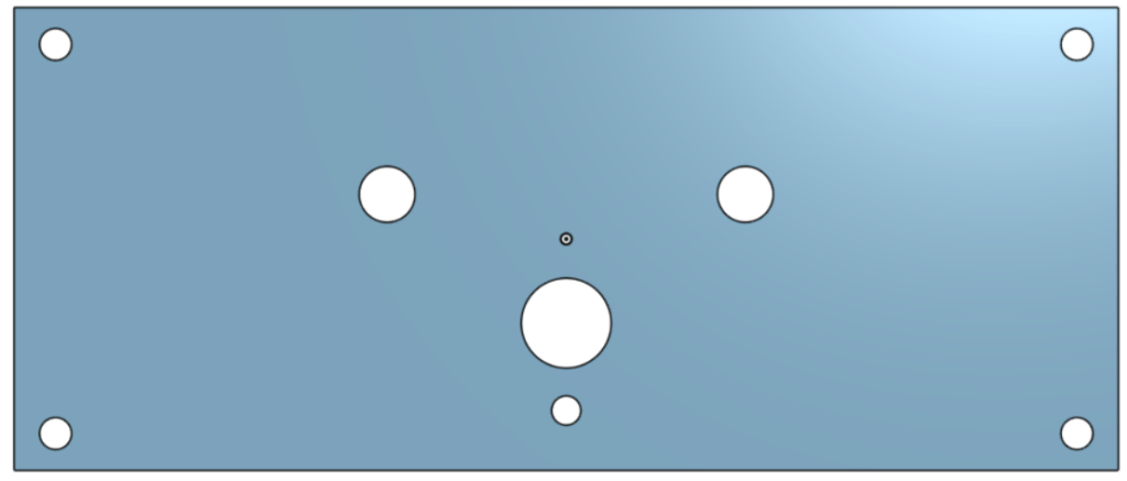
It’s been about a year since then, and I’ve decided to take another stab at it. This time, I’m planning on making something to be proud of. My original design was very simple – just a DPDT toggle switch, some RCA connectors, some wires, and a bit of soldering. For the new box, I wanted to use a rotary switch with a nice knob along with LEDs to indicate the position. My original plan was to match the functionality of the old box with two inputs and a single output. I found some nice looking extruded aluminum enclosures online and used OnShape to model the holes for the front and back panels. I also used InkScape to create precise text and graphic locations that would be used to silkscreen the finished parts.

The aluminum enclosure itself was going to be around $35, plus $40 for the finished plates, plus another $30 for the parts. $105 wasn’t terrible for what I would be getting, but it was a bit pricey and I was worried about the rotary switch wipers affecting the sound quality over time. That’s when I decided to scrap my design and start over. If I was going to spend a good bit of money and time, I didn’t want to match the functionality of my old box, I wanted something better.
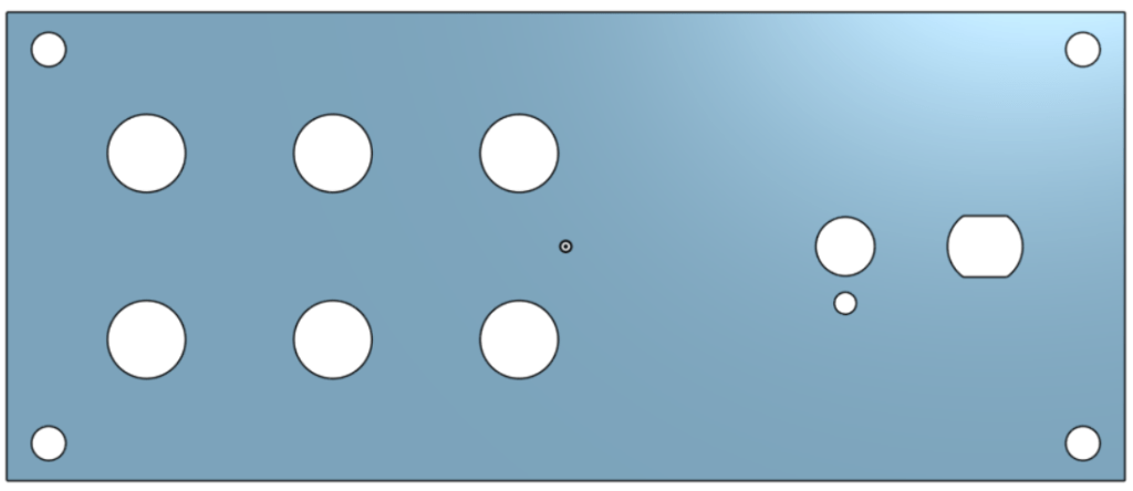
I knew I still wanted a rotary switch on the front. I knew I wanted to have aluminum plates on the front and back so that they could be easily (and cheaply) cut and processed. But I also wanted to have 6 inputs instead of 2. I also wanted to turn this project into more of a learning experience instead of just copying what I had done in the past, so I decided I would design a PCB to perform the switching – something I had zero experience with. I had tried following some basic PCB tutorials in the past, but never ended up finishing them. Now, I actually had a goal in mind. I could make something of my own, and hold the fruits of my labor in my hands when I was done. I was sold.
I started this new design by drawing up a quick schematic in Visio – the tool I have the most experience with. Simultaneously, I started picking out parts from Tayada Electronics, DigiKey, and Newark. I decided to go with an SP7T switch to allow for an “OFF” position. I wanted to use 3-pole relays to switch each channel, but they were much more expensive than the 2-pole variants. So, I was going to use two relays for each channel – originally a DPDT and an SPDT. Later on, I swapped everything to DPDT because the footprints were smaller somehow, and they were readily available.
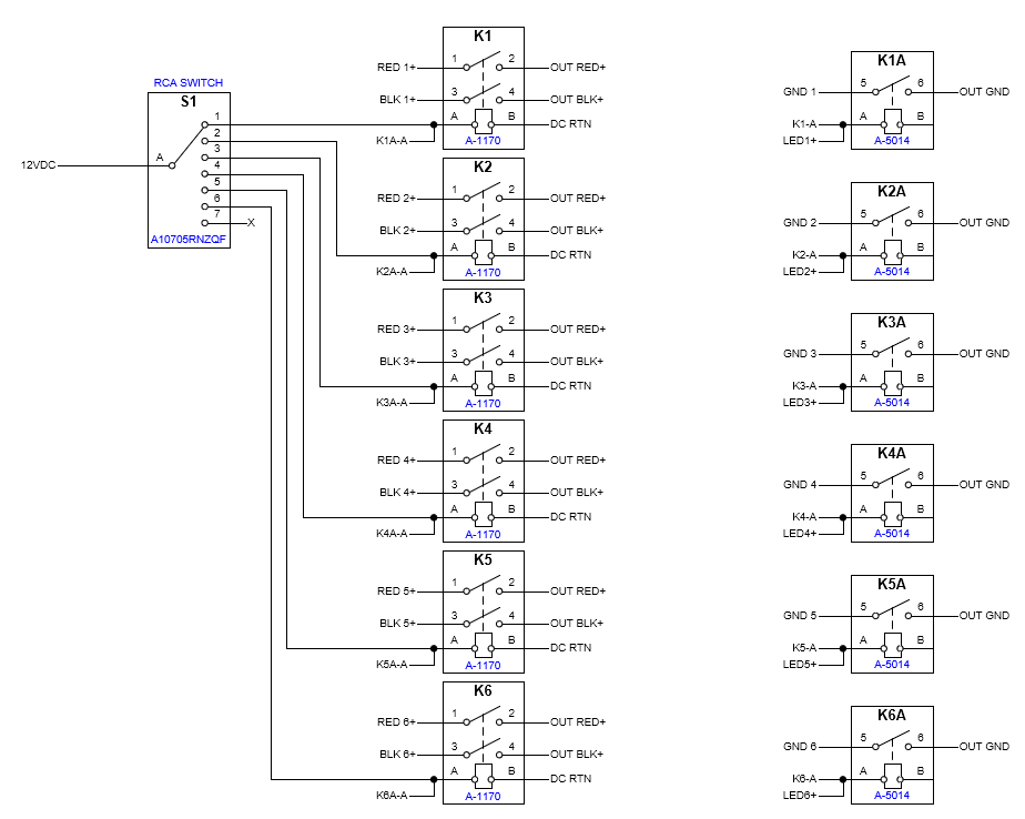
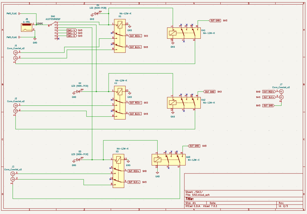
Now that I had a basic idea of the functionality and connections I wanted, it was time to actually design a “schematic” in KiCad (a free, open-source, PCB design tool). I started placing components, based on my Visio schematic. I created new symbols, where needed, and routed everything together.
Next, I ran the footprint assignment tool and created footprints for all of the board-mount components I was going to use. Now it was time to actually create the PCB layout. I opened the PCB editor and started carefully arranging the footprints for the RCA jacks and relays. I also added pads for the input power, rotary switch, and LEDs, and finally added four large mounting holes. This is what it looked like before and after routing all of the connections:
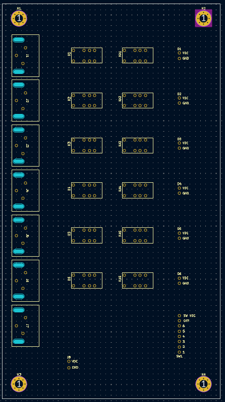
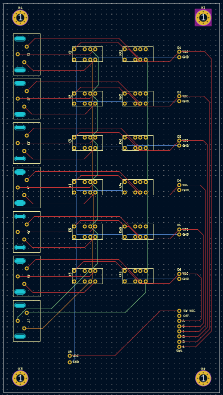
I was really excited to get it in my hands, so I quickly submitted my Gerber files to JLCPCB and got all of the components on order as well. I’ve listed out the components used below. I’ve also included the KiCad project files, if you’re interested in building this yourself!
DOWNLOAD: RCA Box KiCad Project Files
- 12VDC Power Adapter – L6R12H-120
- SP7T Rotary Switch – A10705RNZQF
- Dual RCA Jack – PSG01550
- From Tayada Electronics:
- Aluminum Knob – A-6760
- DC Jack – A-991
- DPDT Relay – A-1170
To be continued in Part 2…
