Background
Sea Ray boats from 1999-2008 used a CAN bus switching system to control components such as the lights, water pumps, bilge pumps, blowers, etc. The Electronic Interface Module (EIM) system was prone to failure over time and had the potential to cause fires. Sea Ray realized this and did away with the EIM system, but left existing owners high and dry to figure out any issues on their own. They do not currently offer OEM replacement parts or alternatives.
My father happens to own a 2003 Sea Ray Sundeck 220 which utilizes one of these EIM systems. He has already replaced it once, to the tune of around $1000, but is already starting to experience reliability issues again. After hearing about this, and realizing that father’s day was near, I decided to take it upon myself to fix this issue once and for all.
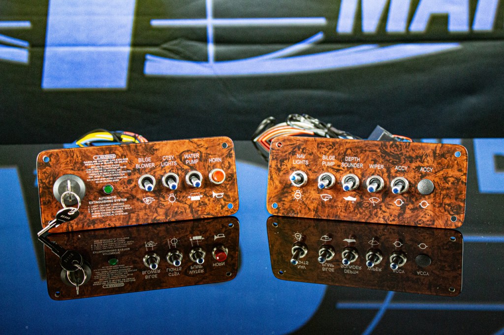
I began doing research on various boating forums, and one company kept popping up as a solution for this issue – Flounder Pounder Marine. They make a full system replacement that bypasses the EIM entirely and uses high-current switches to actually make/break the circuits, rather than relying on a unnecessarily complicated circuit board and relay scheme like the old EIM. These FP Marine replacements look professional and require only slight modification to the fiberglass dash to allow room for the switches and wiring. However, they also cost around $1000 and didn’t quite have the “cool” factor that both my father and I thought they should. DIY is more fun, anyway!
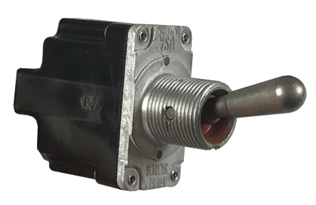
Originally I wanted to go with basic metal toggle switches with separate panel-mount indicator LEDs – a classic go-to for industrial and military systems. This type of system was familiar to me, having worked at various defense contractors my entire career. I had switches and LEDs in mind that I had used on systems destined for extremely rugged environments and was confident they would last. However, like the FP Marine design, it lacked a certain “cool factor” that my dad was looking for.
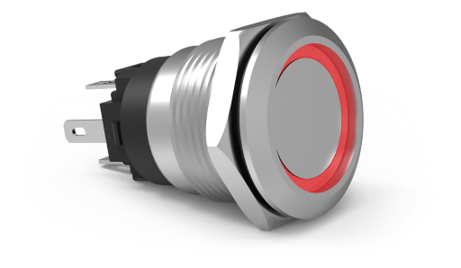
We decided instead to go with illuminated anti-vandal switches. I’ve always liked the look of them and as soon as he saw them, he was convinced as well. We went with the AV Series switches from Carling. They’re weather resistant to IP67 and seal to the front of the panel using an o-ring. The built in LED ring is independently controlled. They make both momentary (for the horn) and maintained (for everything else), and they have a current rating of 10.1A, resistive.
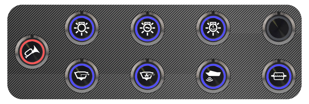
Once I found my switches, I made a quick mock-up in Photoshop, based on the existing buttons on the EIM-based switch panel:

From there, I began the design process. I was able to find the schematic for the boat online, and realized that I could replace the EIM system and switch pad without impacting any other wiring. I just needed the pinout of the “main harness connector” which used to connect to the EIM. Luckily for me, the schematics were detailed and easy to understand. I knew which pins controlled what components, and I started drawing up my own schematic for the switch panel and fuse block. I went back and forth between my own schematic and the one included in the boat manual and came up with something to replace any important functionality. The schematic for this project and be downloaded below:
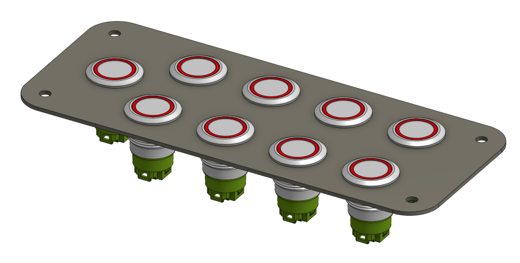
Now that I had my schematic ready to go, I had to start working on the mechanical portion to ensure that my vision was actually possible in the real world. I took some basic measurements of the old switch pad, gathered some info from the datasheets, and was lucky enough to find 3D models of the switches I planned on using. I then used OnShape, a cloud-based 3D modeling software, to create a model of the switch plate, including the switches! To my surprise, my original Photoshop mock-up wasn’t too far off. I made sure to leave some room around the edges, where I planned on putting a rubber seal, and enough room between the switches to tighten the nut.
Now that I had verified everything would fit properly, it was time to start building a BOM and purchasing materials. I decided to use DigiKey – an electronics distributor that I often use for work. They have an excellent sorting and filtering system to help narrow down results, and an availability or price sorting function that allows you to skip any components that are too expensive or not readily available.
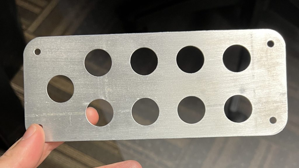
Now that everything was on order, it was time to get the switch plate made. I originally considered getting a quote from an online vendor for a custom, fully carbon fiber plate, but decided it would likely be more cost effective to simply machine it and cover it with a carbon fiber vinyl. I ended up exporting a DXF from my 3D model, and using some scrap 1/16th thick 6061 aluminum plate. I was able to have a coworker water jet out the plate, and as you can see, it turned out perfectly!
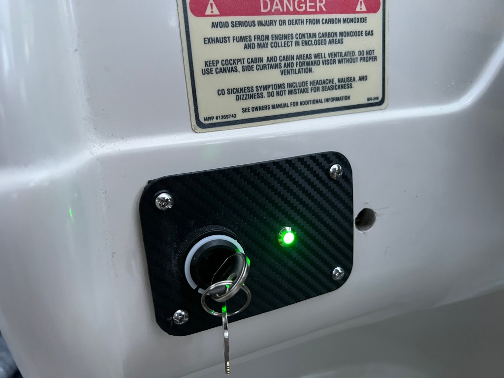
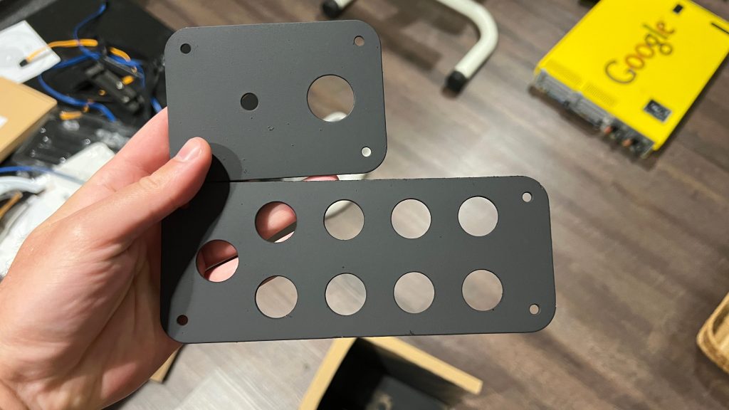
The next step was sealing the plate. Although 6061 has excellent corrosion resistance already, I decided to use some automotive primer and enamel spray paint to provide additional protection. After cleaning the aluminum with soap and water, I wiped it down one last time with alcohol in preparation for the primer. I gave it a few coats of primer on each side, topped with a couple coats of paint. After letting it dry overnight, I came back to check on them. It wasn’t a perfect finish – a couple bugs had gotten stuck to it and a snail had slithered over one of them, but I figured all of those blemishes would be hidden by the carbon fiber, and I was too excited to wait, anyway. Note – this picture also shows the ignition switch panel that I made concurrently. There wasn’t nearly as much design work involved, since I was basically just replacing the existing panel but not the electronics.
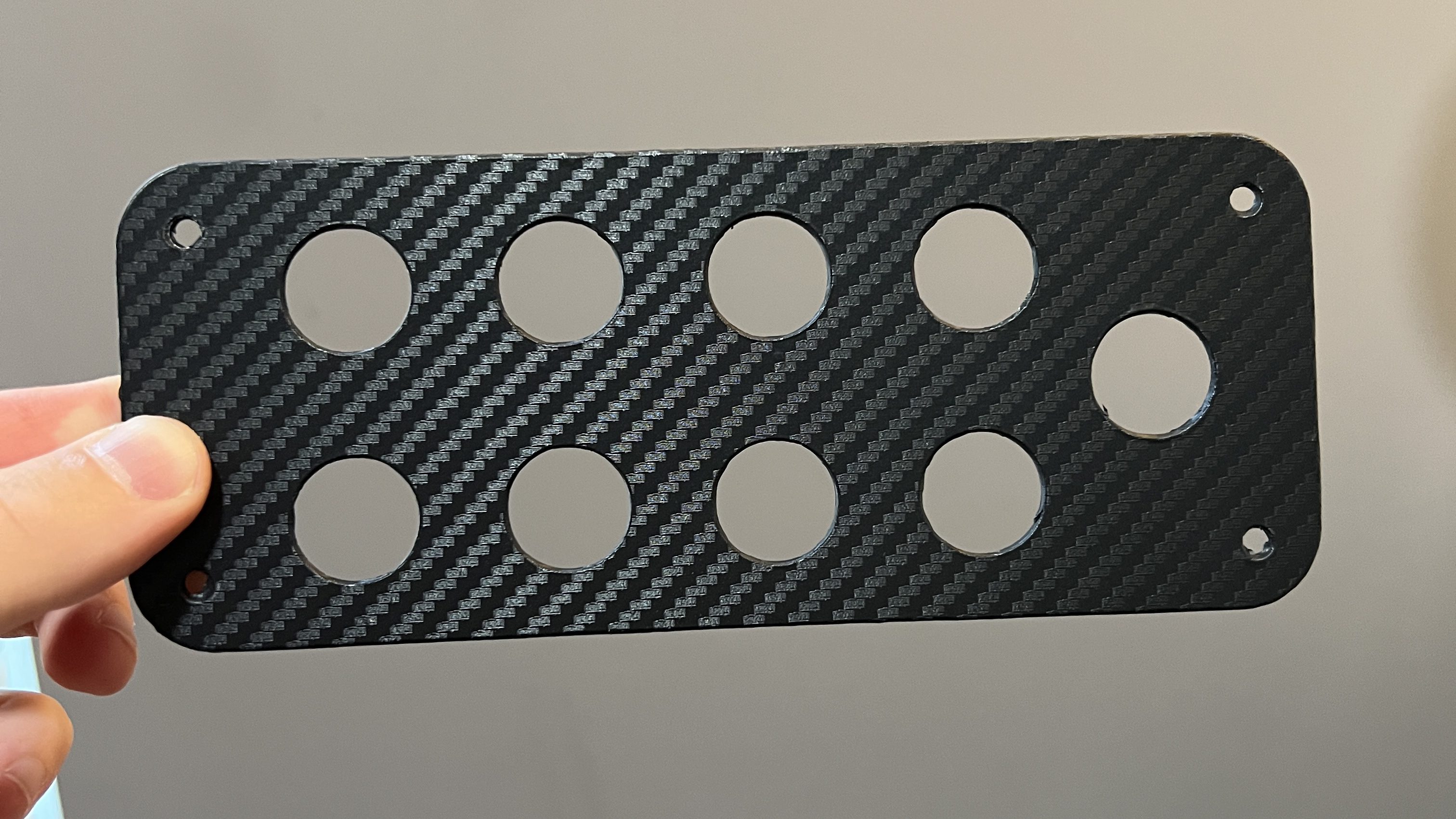
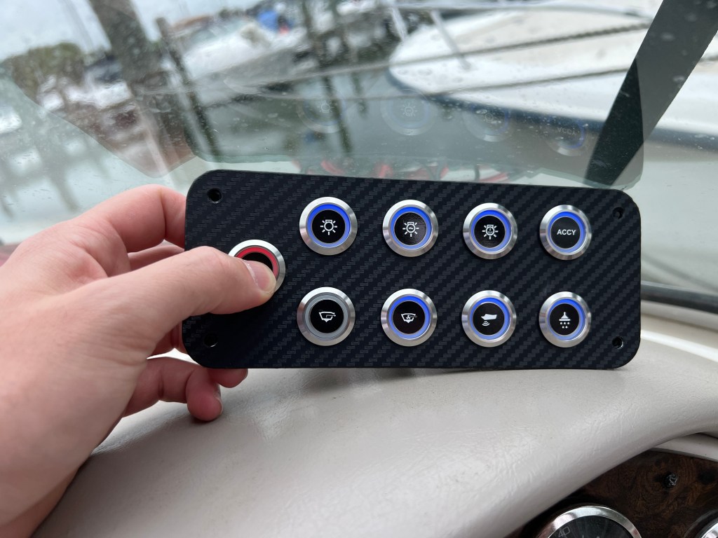
Next, I applied the carbon fiber vinyl to each panel. I used a heat gun to help mold the vinyl wrap around the corners and into the switch wells. I used a pen to push down on the switches to help make a nice indentation and form the vinyl around the switch holes. Then I cut out each switch hole, and cut the border, making sure to burnish any edges and apply some heat to help it stick. Finally, I had a “finished” switch panel that looked incredible.
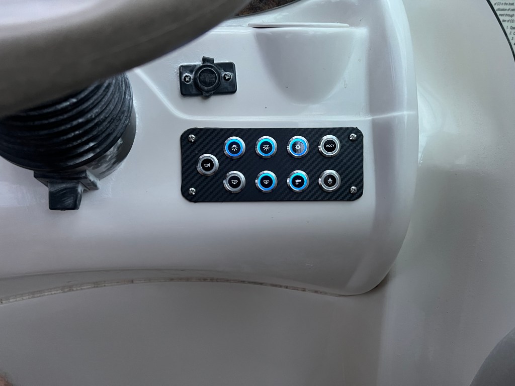
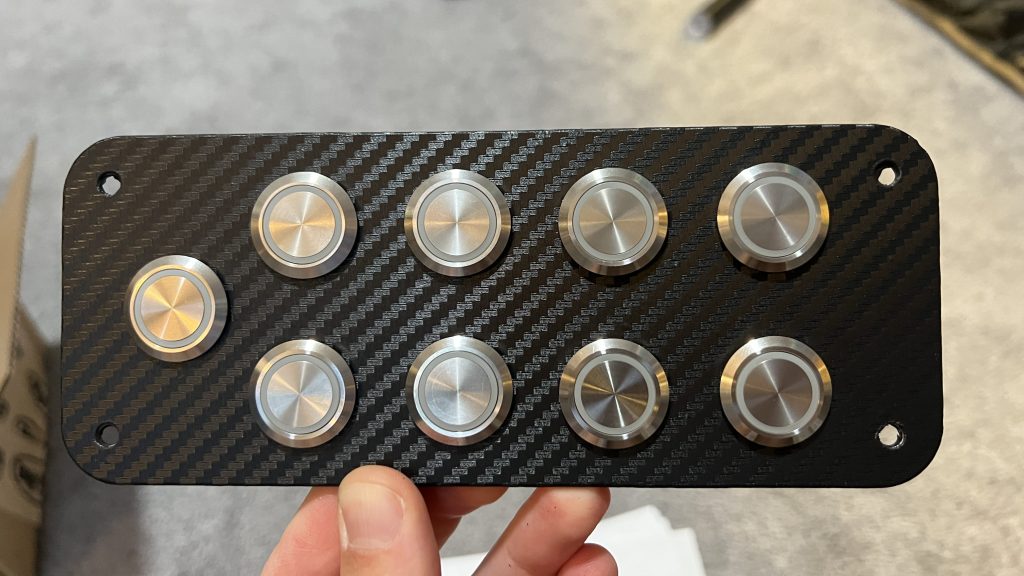
I went to add the switches, but realized the carbon fiber had made the holes a bit too snug, so I traced around each hole with an exacto knife, being careful not to disturb the front finish. I was able to slip each switch into place and secure them with lock nuts. Next, I cleaned each switch with rubbing alcohol to remove any oils from handling and applied the labels that I had custom printed from Avery. Shout out to Avery – they were the only online label retailer that custom printed 0.5″ round labels.

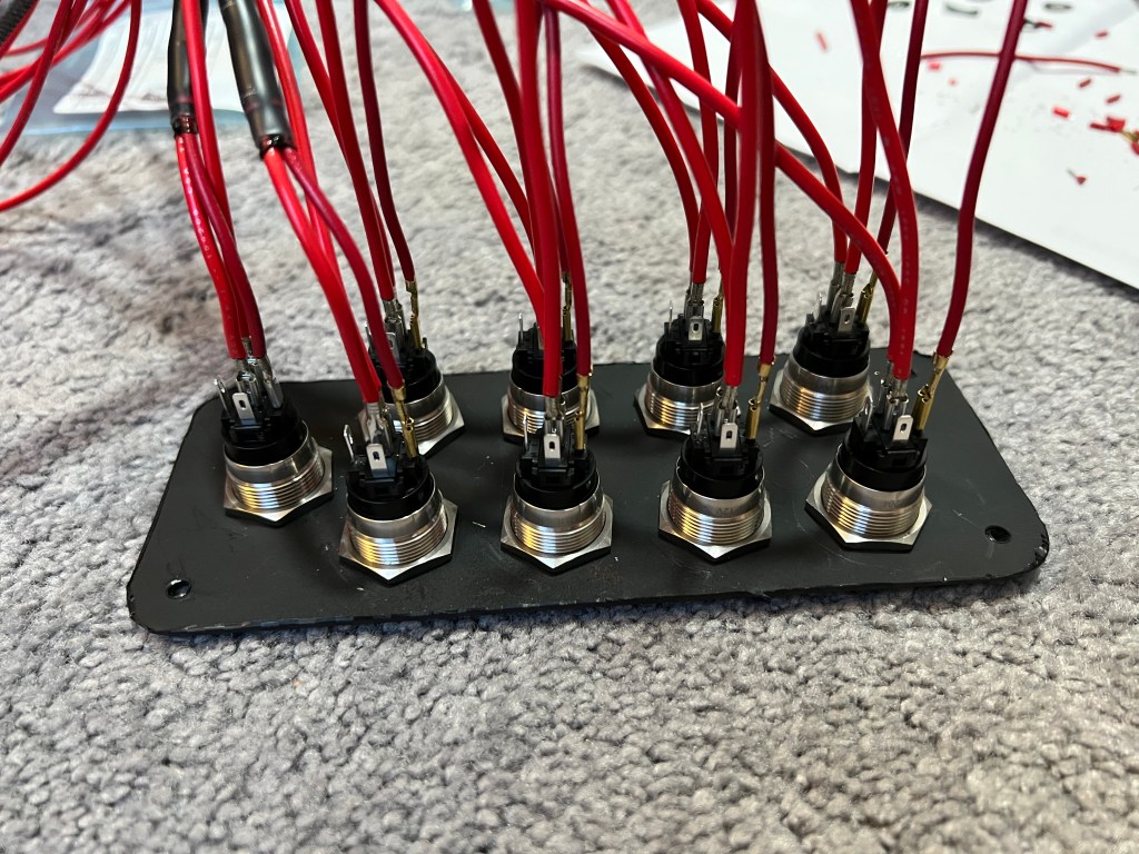
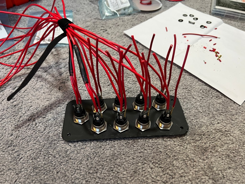
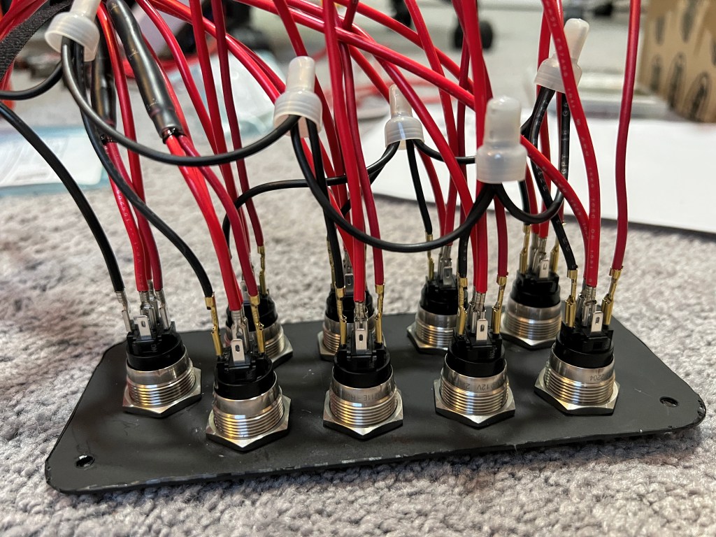
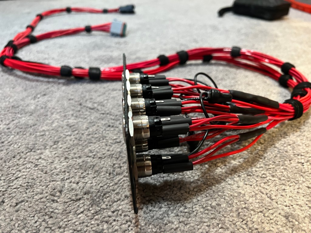
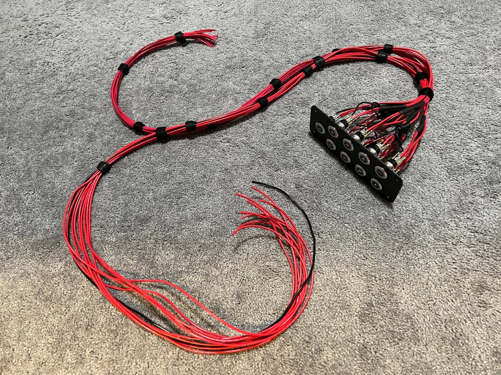
Now that I had my switches installed, it was time to begin the wiring process. I used 14AWG wire for the COM and NO connections. I added an 18AWG splice from the LED+ terminal to the NO terminal to illuminate the ring when the switches are activated. The LED- terminals were all jumpered together using black 18AWG wire and insulated closed-end crimp splices.


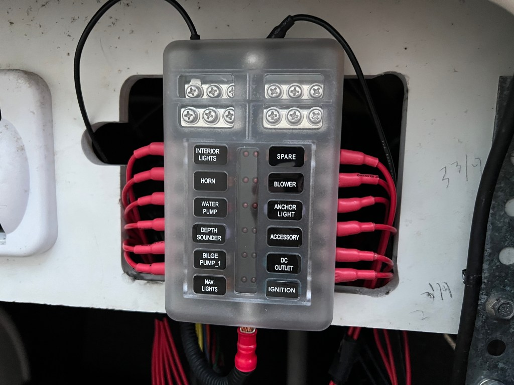
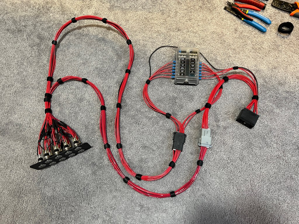
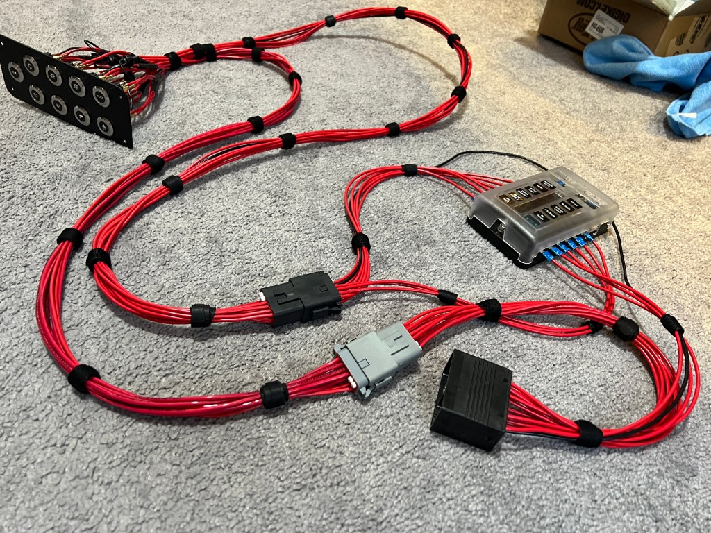
The fuse block was next. It acts as the “central hub” of wiring that connects the main harness connector and the switch panel together. The leftmost connector is what powers each of the switches. The middle connector takes the power from the switches and connects it to the rightmost connector, the main electrical harness connector. All the connections to the fuse block are made with crimp barrel ring terminals. The crimps were covered with adhesive-lined heat shrink for added protection against moisture.


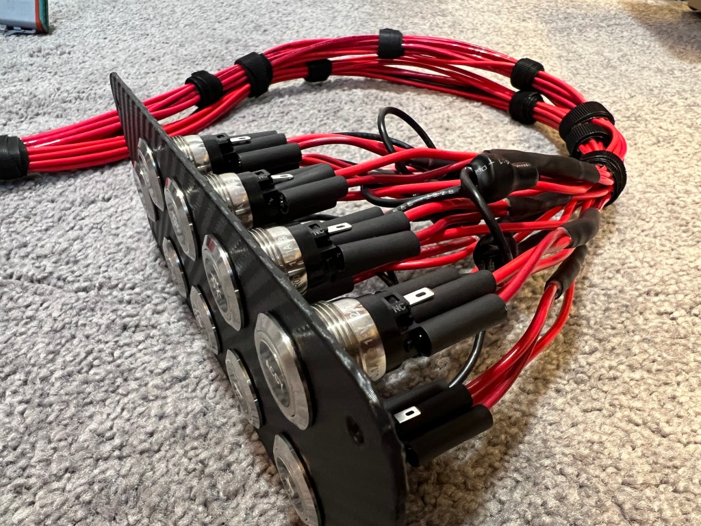
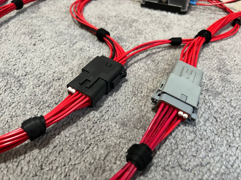
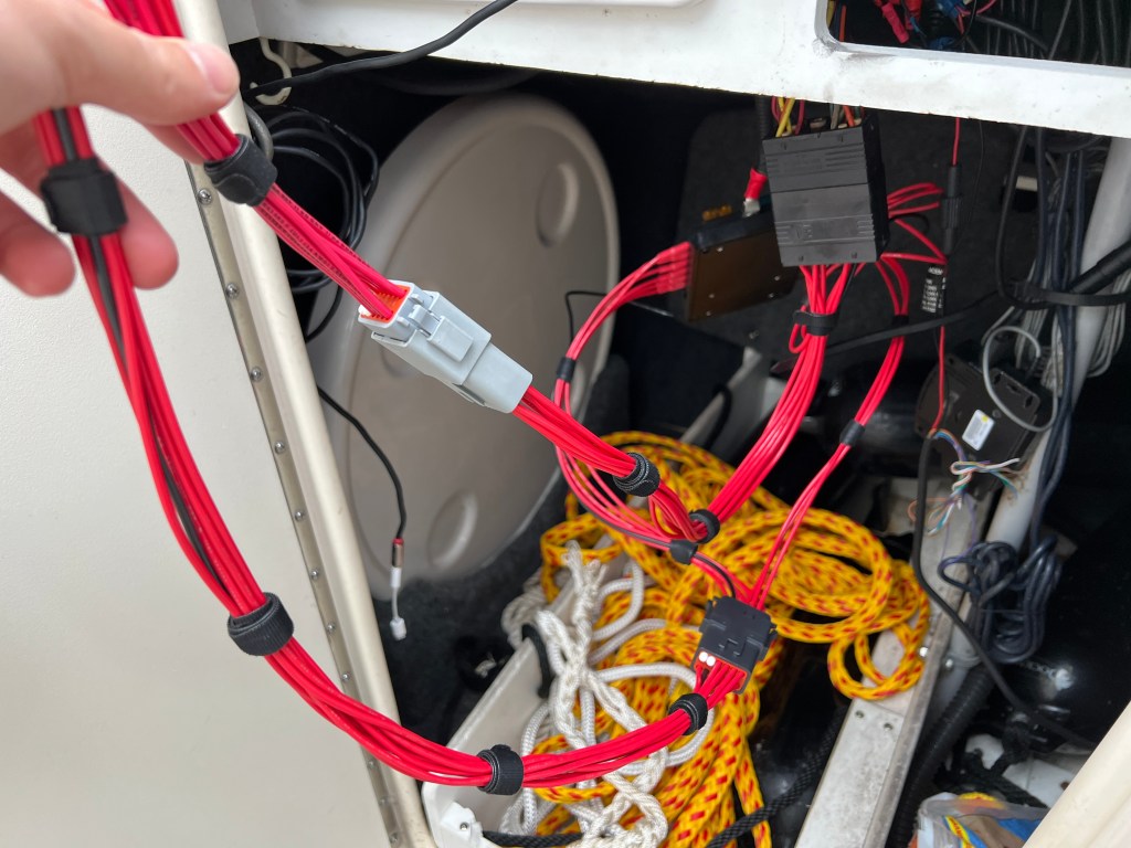
For the connections between the main harness/fuse block and the switch panel, I used Amphenol 12-way, AT-series connectors to make installation/replacement much easier than hard wiring. Now that I had both the switch panel and the fuse block harnesses built, it was time to do a test fit and see how it looked! Everything fit perfectly and looked nice and neat. I tested the functionality using my multi-meter to verify the switches were connected to the correct terminals all the way from the fuse block to the main harness connector.
I was finally ready to test my design! I met up with my dad at the marina, and we double checked to make sure everything worked before we installed the new system. His horn has been acting up lately, so that’s something we took note of. We turned the battery off and I started removing the main harness connector from the EIM. When I went to plug my harness in, I was having a good amount of trouble and I realized the old seals were quite dry and needed to be greased, something I’ll keep in mind for later. I got everything fully mated and we turned the battery back on – it was the moment of truth.
I pressed all of the buttons and only half of them worked. I got really worried for half a second until I remembered that I needed to swap over some fuses from the EIM to my fuse block. After the swap, everything worked properly and I was finally able to see the switches in their illuminated form. I think they look really good – and hopefully not too blinding at night!
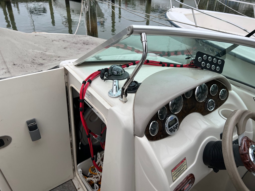
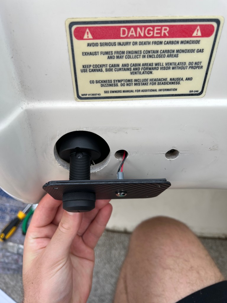
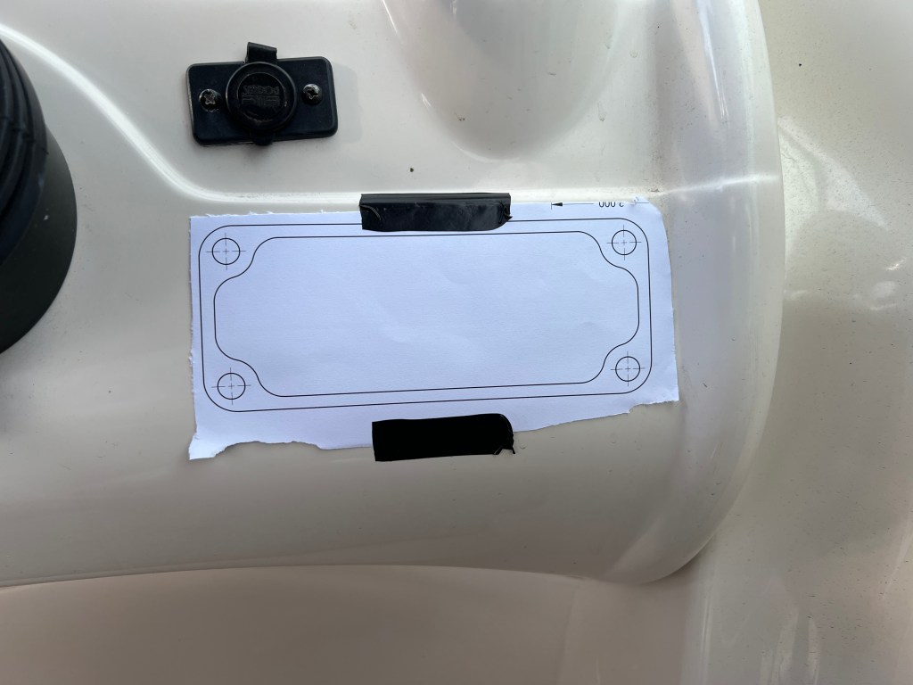
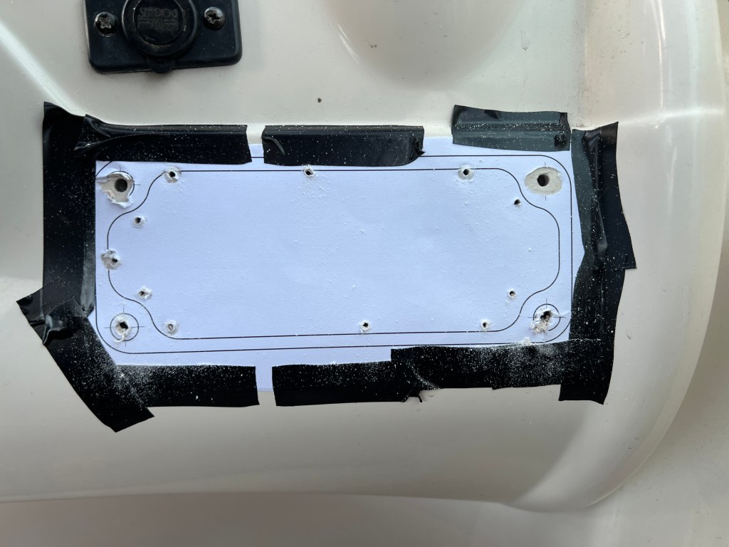
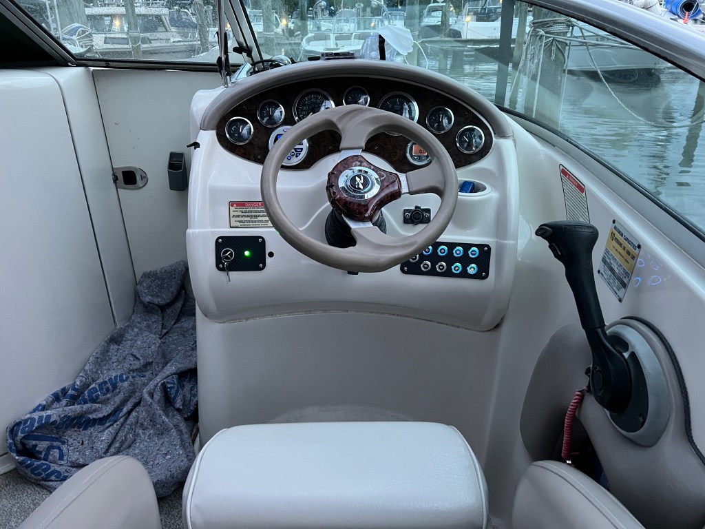
A couple weeks later, we had the chance to do the actual installation. First, we removed the old system entirely. I then connected the necessary wires for the ignition switch and LED, since that side didn’t require any fiberglass modification. We match-drilled the holes, and installed the screws and nuts. Unfortunately, I forgot there was an additional hole, so at some point we’re either going to fill it or make another plate that’s slightly longer to cover it. Next, I taped the guide drawing onto the dashboard and drilled out the screw holes and some small holes along the perimeter, for reference. I used a Dremel with the cutting wheel attachment to cut the main portion out and then the grinding wheel to finish the hole and smooth it out. We installed the screws and then mounted the new fuse box in the same location as the old EIM. Next, we connected the main harness connector and the two harnesses from the switch panel. Finally, it was the moment of truth. We turned the battery on and…nothing. Luckily, I quickly realized that I had forgotten to connect the main power line to the fuse box. After fixing that small mistake, everything worked perfectly – and it looks beautiful! It wasn’t quite OEM-level as far as the fit and finish, but I’m still really happy with it. I’ve also learned a lot for next time (if there is one). Thanks for reading, I hope you enjoyed!