Note: If you would like to attempt this project yourself, a .zip file is included at the end of this post which contains the Arduino Code, Home Assistant Code, Bill of Materials (BoM), Schematic, 3D Model, and more!
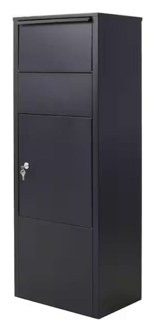
Approximately one year ago, my partner and I purchased the Eufy Smart Drop S300 (sometimes known as the T8790) to help prevent the rampage package theft that occurs in our neighborhood. People in this area often buy delivery boxes with ports that allow packages to be deposited but not removed, much like a USPS mail drop box, only in a smaller form. The problem with this style is they aren’t space efficient. The package port takes up a bunch of space up top, and also heavily limits the size of package it can receive. Many of these style boxes are also extremely expensive for what they are. For example, the simple (small package port) model below is over $300!
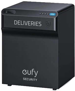
The Eufy is built different. It doesn’t have a silly package port. It’s got a spring-loaded, hinged lid which allows full use of the interior space. We purchased ours for $120 back in June 2024 and have been loving it ever since. There were some areas that needed improvement – the camera quality and FPS was poor, the WiFi connection was spotty, and the app was a bit clunky, but overall, it was still great! Even if it took a couple tries, we were able to set different codes for different deliveries, set temporary codes, remotely open the box, etc. All the things you want from a secure package delivery box.
While the software wasn’t the most polished, the mechanical design seemed really nice. The metal enclosure is sturdy, the design is sleek, and the springs are strong and easy to replace. Ignoring the electronics, this box could easily last 10-15 years outside. Unfortunately, we cannot ignore the electronics, and they were sadly not built to be long for this world. After only a few months, the camera lens began showing signs of condensation and stopped working shortly thereafter.
A few months later, the box completely stopped connecting to WiFi or the phone app. We attempted a factory reset, but the unit wouldn’t even respond to input from the reset button. We left it outside since the existing passwords were still working, but we couldn’t change the passwords or add new ones. I contacted Eufy support hoping they could just send me a replacement Function Panel, but they informed me that the Smart Drop S300 was now discontinued. I figured, as I had shopped around a bit already and didn’t see them in stock anywhere. It’s a shame, because this product is such a good start. They don’t even need to redesign the box, just the Function Panel!

Finally, just a couple weeks ago, the box finally died for real. The button pads were totally silent when pressed, and we had to open it using the physical key. We left it outside a few days, hoping it may spring back to life, but it never returned. Truly a sad day. When it originally lost connection to the app, I started thinking about how I could Frankenstein a solution. I figured the buttons could be hooked into an Arduino or an ESP32 and somehow electronically unlatch the box, but at the time I didn’t have a clue about what the internals/components looked like and didn’t want to break it trying to find out. Well, now that there’s nothing left to break, I decided to give it a shot!
Eufy SmartDrop Tear-down
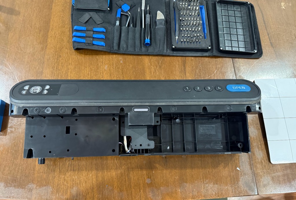
The first step was to remove the “Function Panel” from the rest of the Eufy enclosure. This involves removing the battery and 11+ screws from the inside of the unit. Here’s a super helpful YouTube video which explains the process: How to Replace the Function Panel of eufy SmartDrop
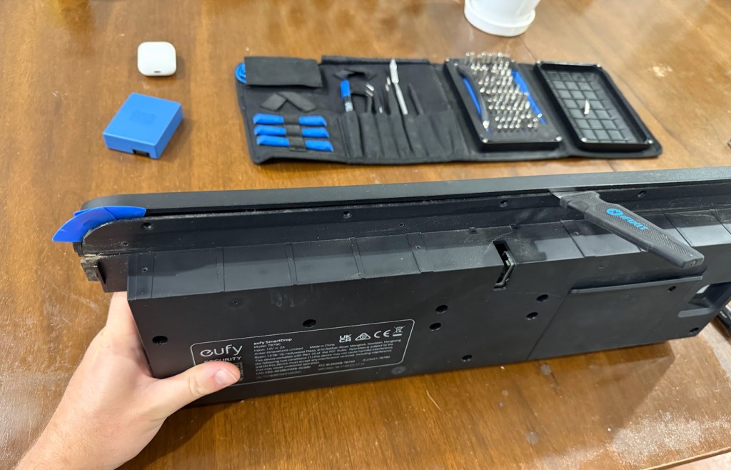
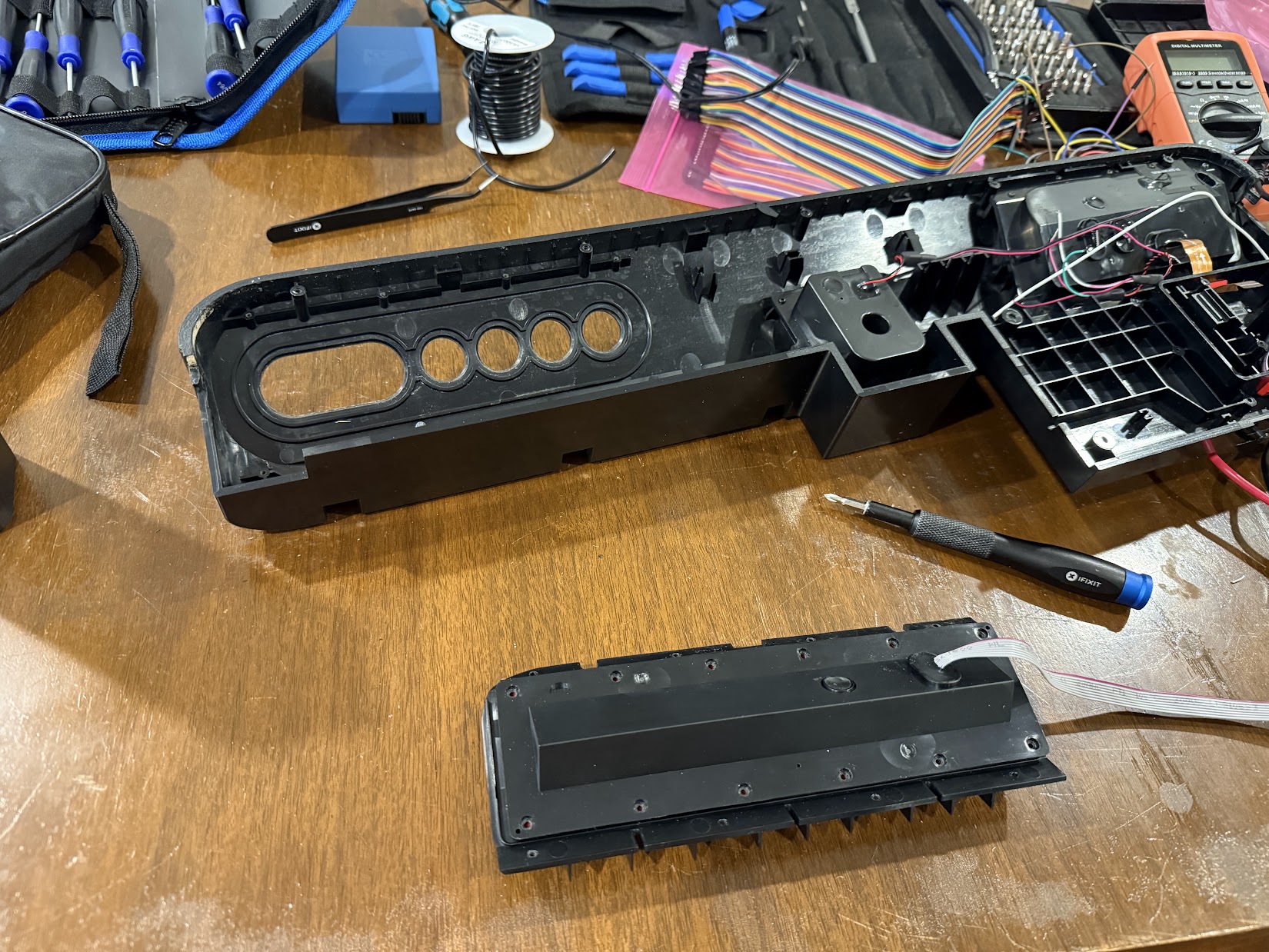
To split the Function Panel apart, there were ~19 total screws that I needed to remove. At that point, I was able to work a pry tool and guitar picks between the two halves. I worked my way all the way around, cracking open the plastic retaining clips as I went. This part wasn’t easy and I definitely mangled some of the edge by forcing the tools in. The guitar picks were helpful to keep split areas open while I worked around the edges.
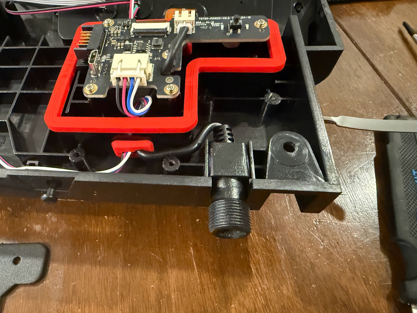
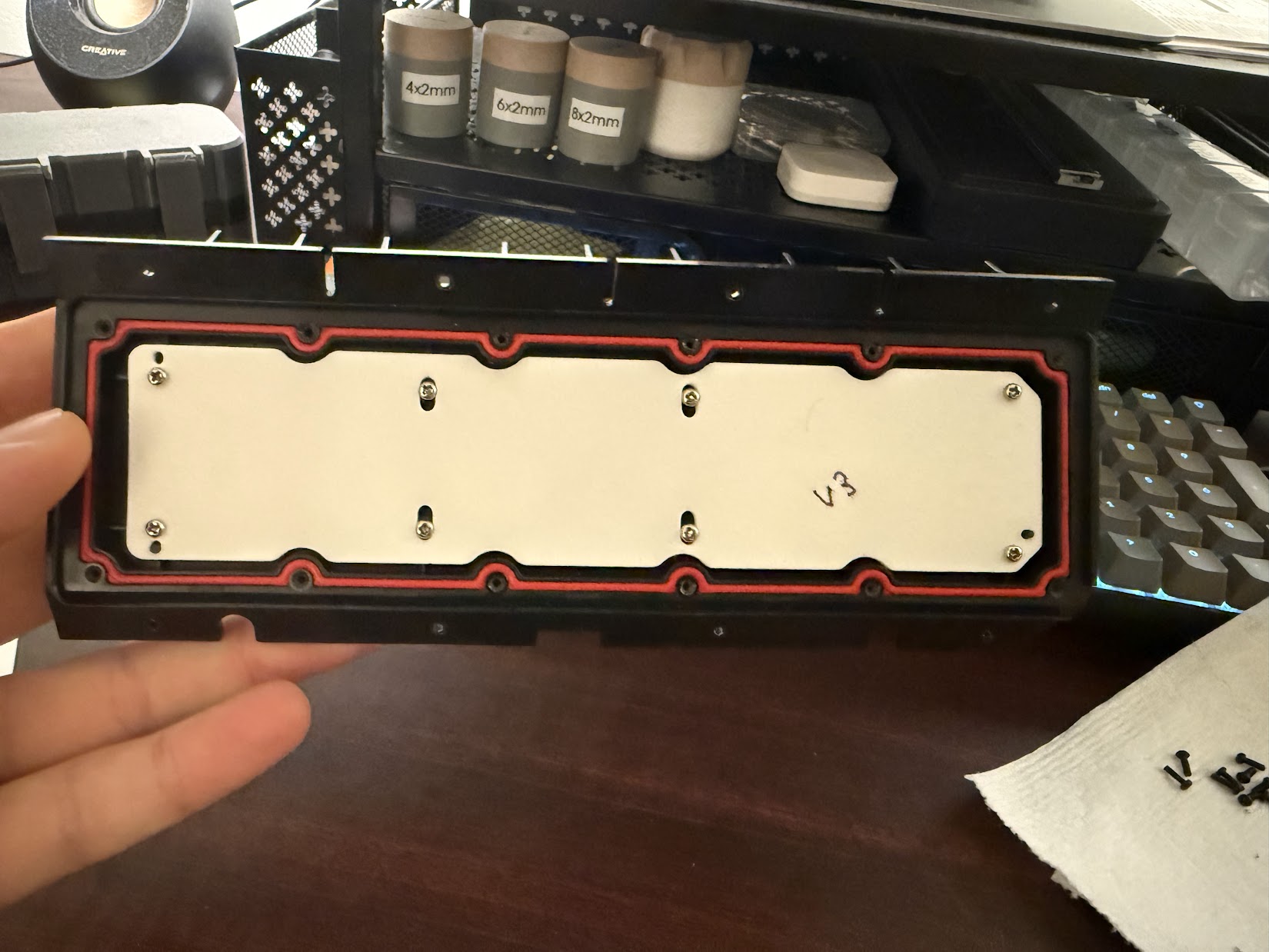
Finally, I was able to split the two halves of the Function Panel. Figure 8 shows the initial view when it was opened. The red outline is a gasket that protects the “Power PCB” which takes in the 12V jack power, distributes it to the camera/brain board, and controls/monitors the latch assembly.
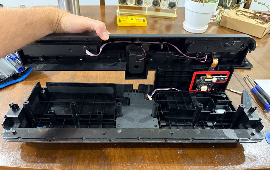
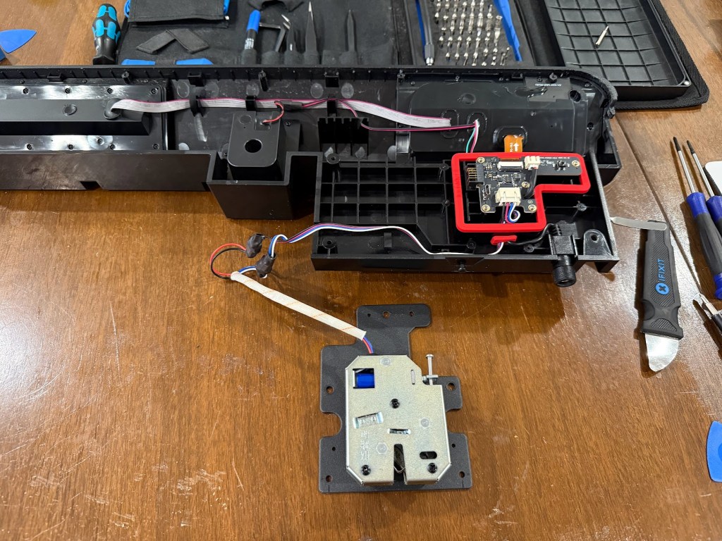
After removing the shell, it’s much easier to see how the electronics are laid out. The 12V jack feeds the “Power PCB” contained within the red gasket. The silver module at the bottom is the latch assembly which utilizes a solenoid to open the lid latch. It has four wires – two for the solenoid power and two for the lid latch sensor. The Power PCB is connected to the “Brain Board” by an orange ribbon cable. The Brain Board has several other cable entries as well – a gray ribbon cable which connects to the “Button Board” and a couple wires.
Latch Module Assembly (AS. 5873X. 5A02-02)
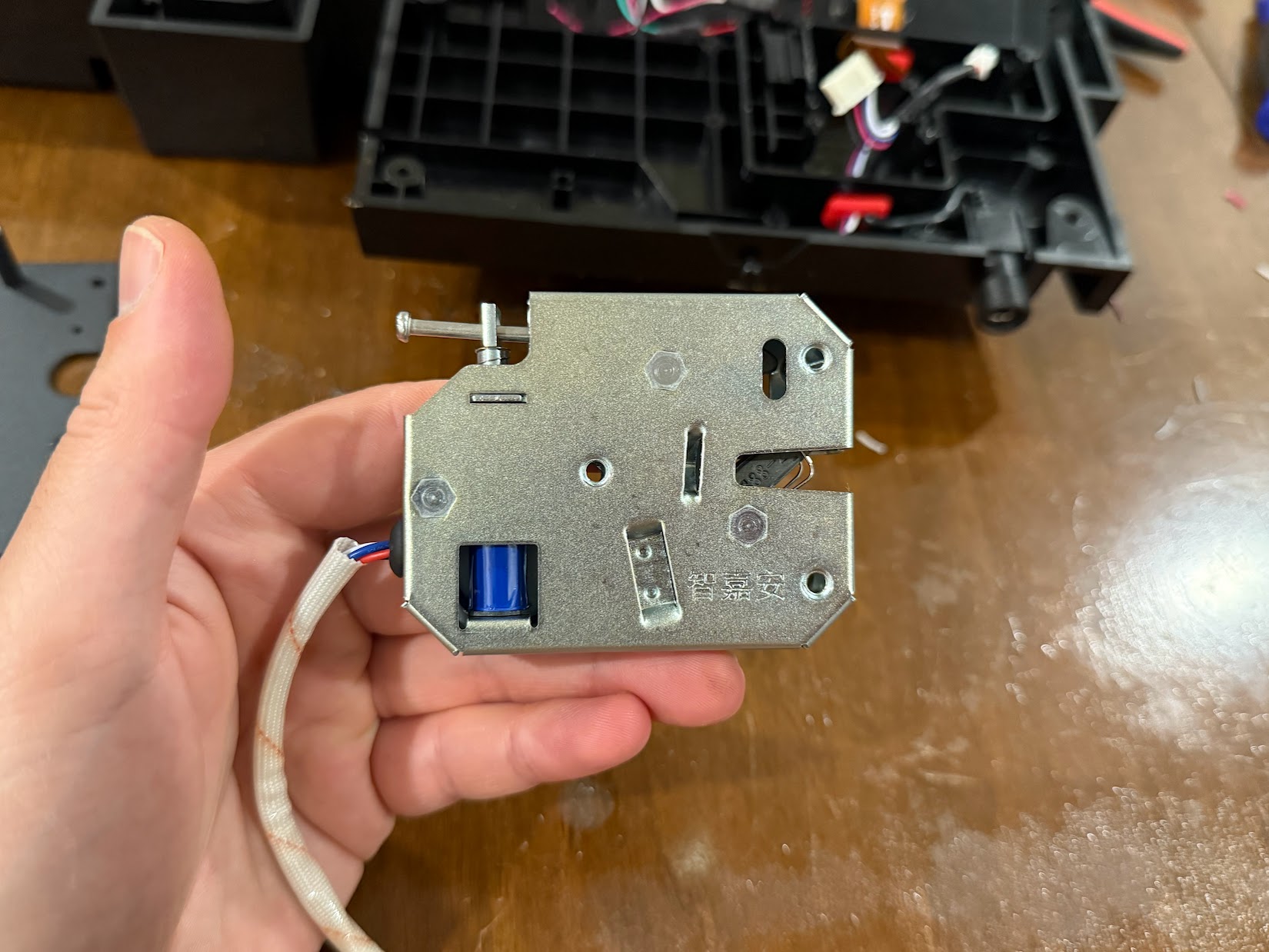
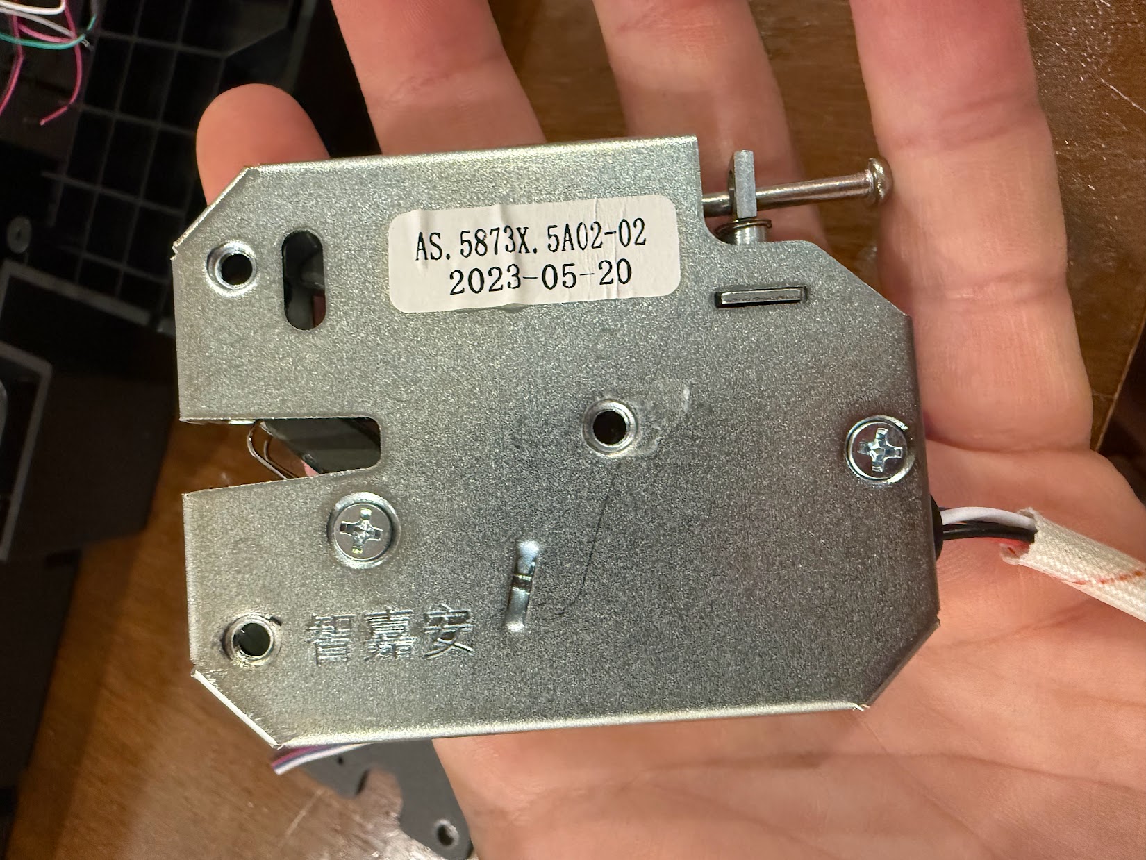

The latch module is a Commercial Off The Shelf (COTS) part. It consists of a metal housing, a mechanical latch, a release solenoid, and a latch sensor to read the position of the lid. I was able to find similar modules listed on Amazon as “Solenoid Cabinet Spring Lock, almost the exact same style – so luckily this seems to be an easy replacement if it ever fails.
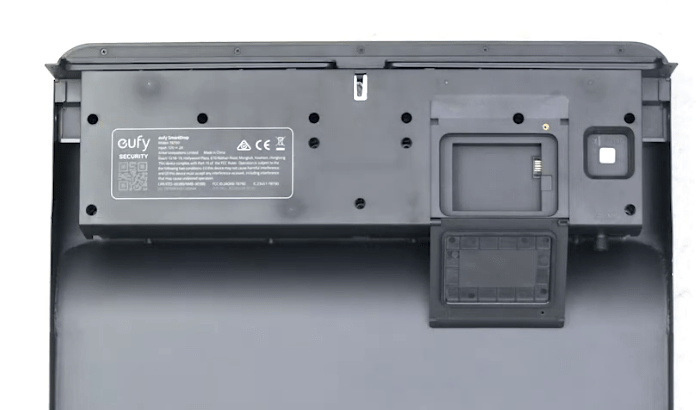
Power Input PCB Assembly (T8790-POWER-V0.5)
The four colored wires (RED, BLK, BLU, WHT) connect to the latch module. The small 2-pin connector is the DC Jack input, and the orange ribbon cable connects to the Brain Board. All connection holes are potted and seem well sealed. 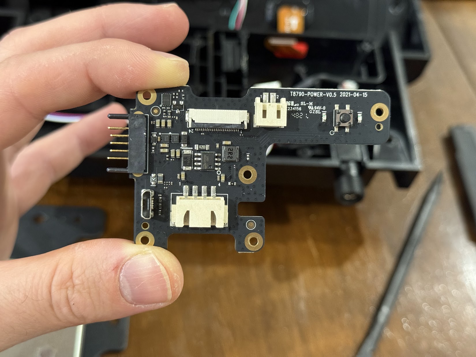
In this picture, you can see the tactile button which is the SmartDrop’s native reset button. There is also a Micro-USB port which is not normally exposed. Possibly used for programming at the factory. 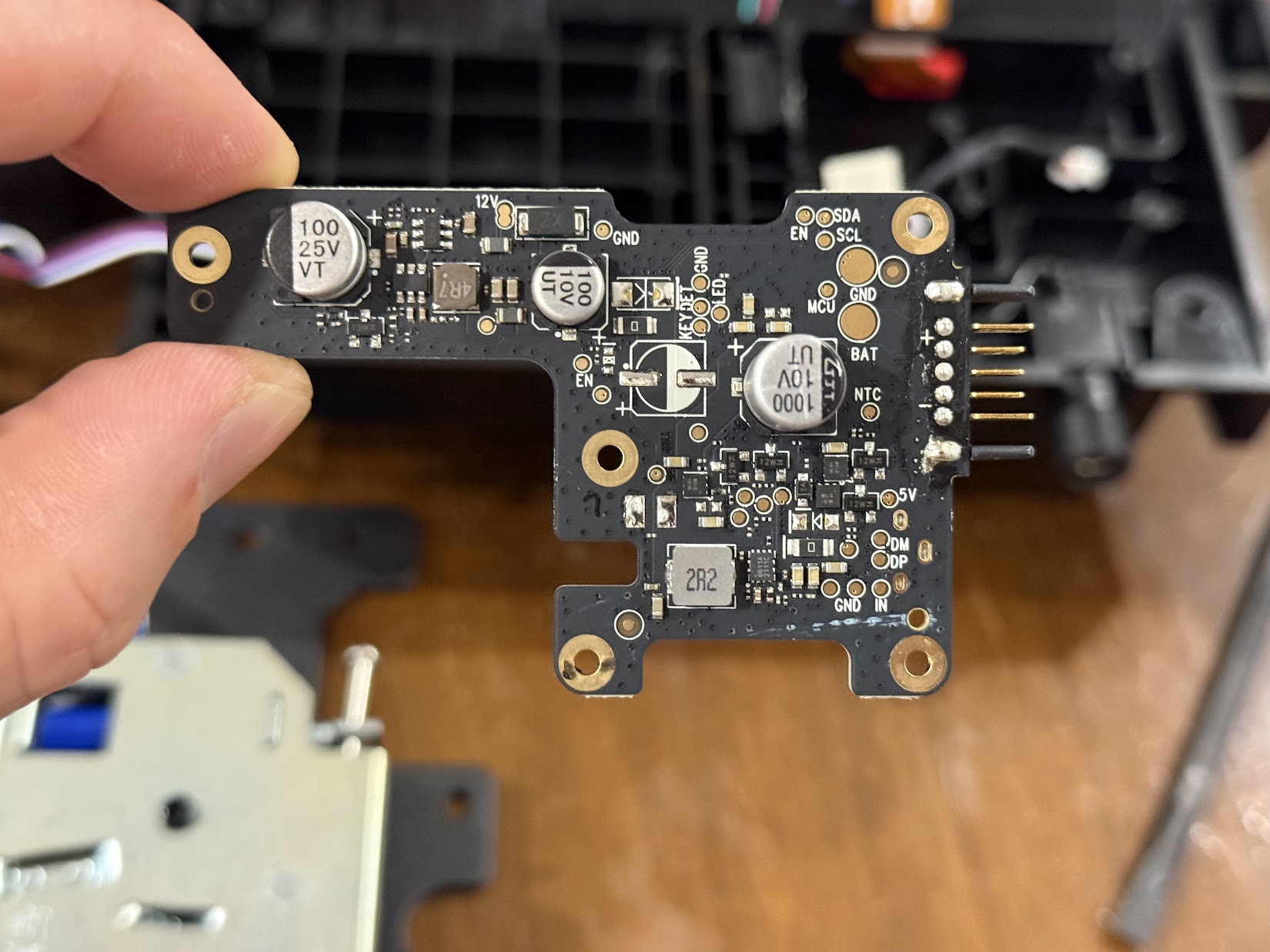
Power PCB Back
Camera/Brain Board Assembly Tear-down

Next up is the camera/brain module. 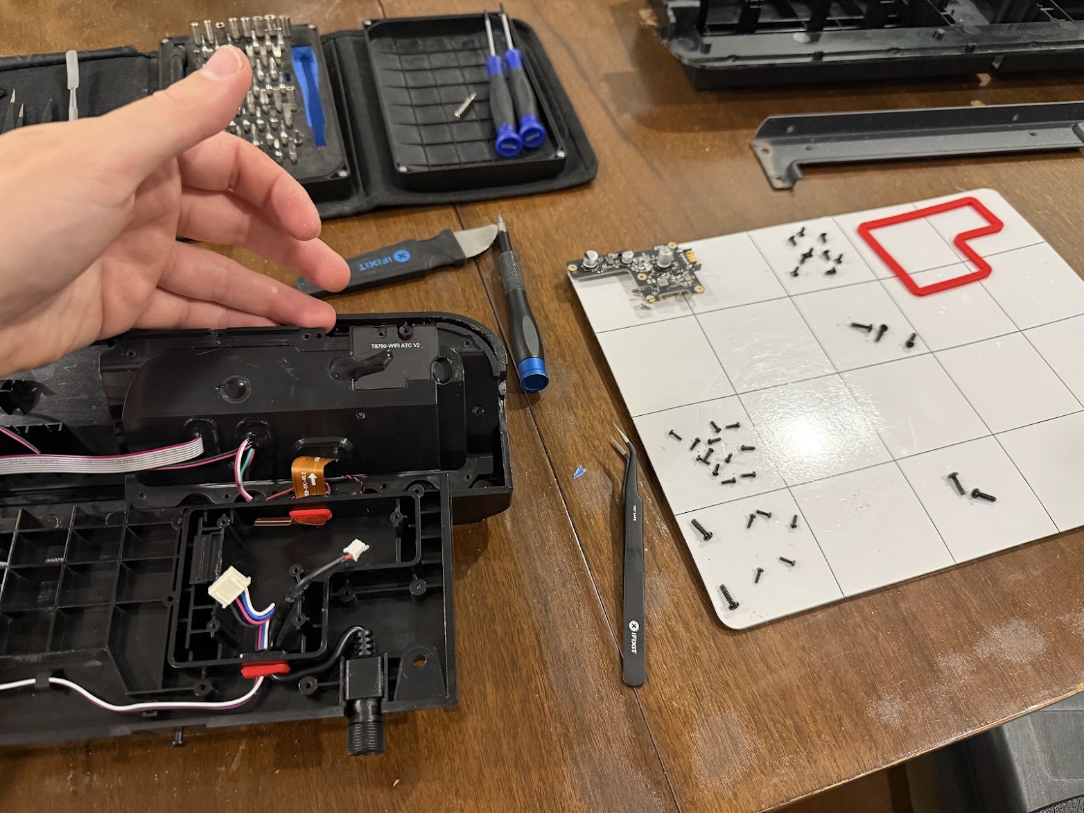
I removed the 12 small screws holding it in place. 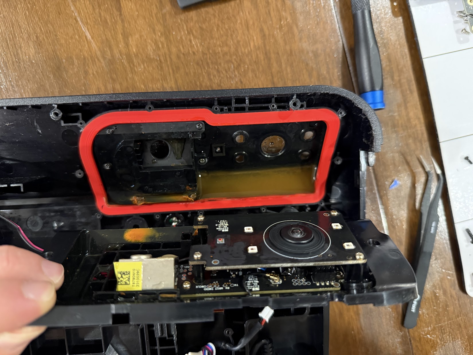
When I pried it open, the cause of death was quite clear. There was a half inch of standing water and corrosion on all the components. It didn’t smell great either. 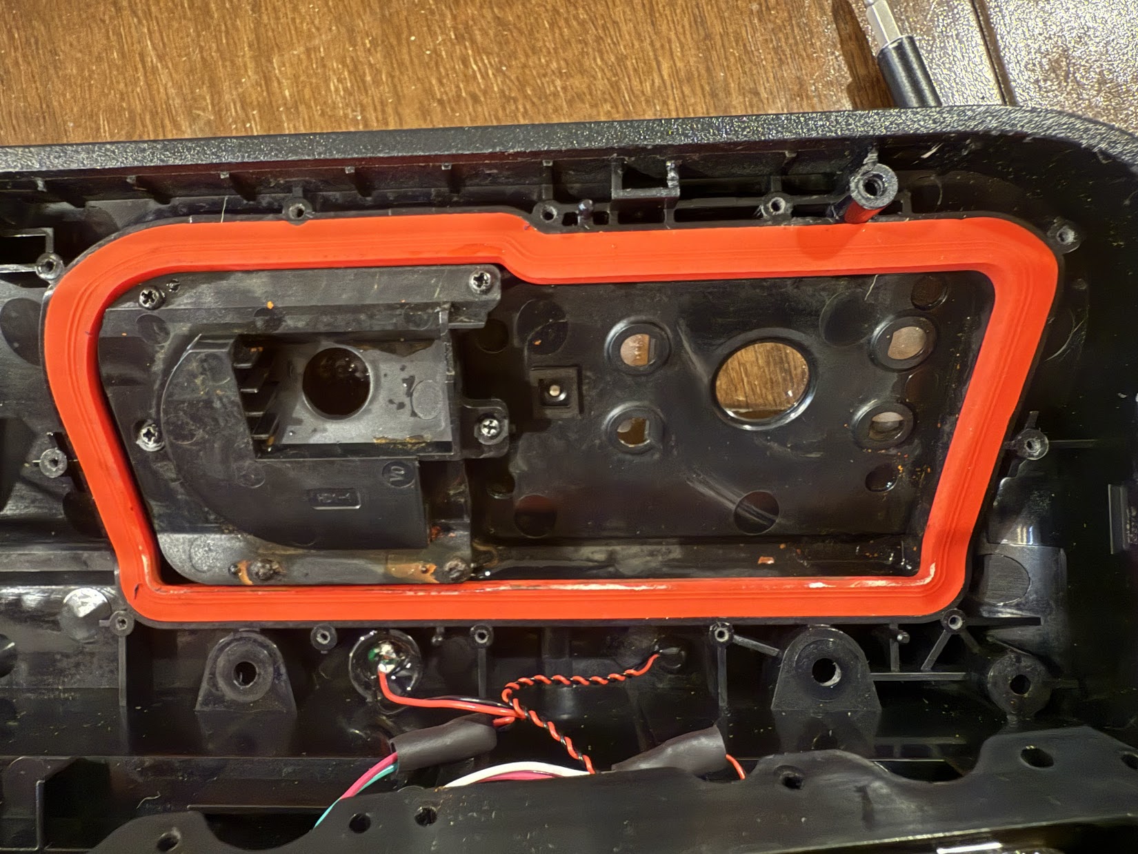
After cleaning out the water and condensation, it looked a bit better. 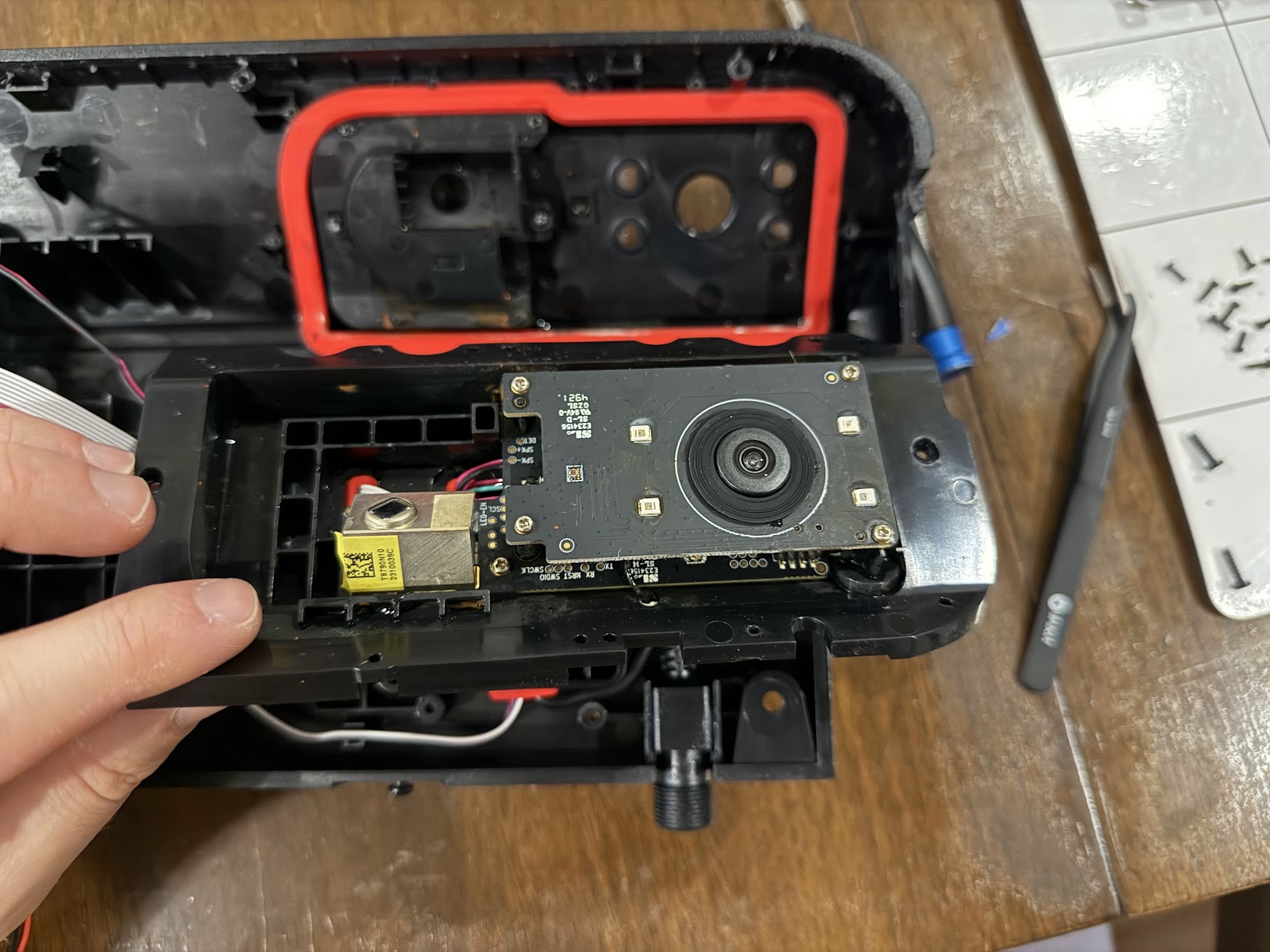
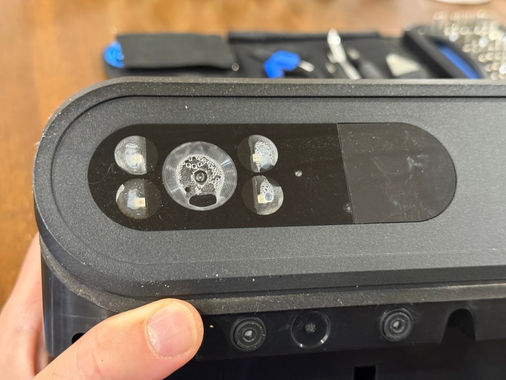
The camera/brain board has a raised daughterboard which houses 4 IR LEDs and the seal for the camera. I believe this is where the moisture infiltrated. 
The top of the IR LED Board which contains the leaky seal. 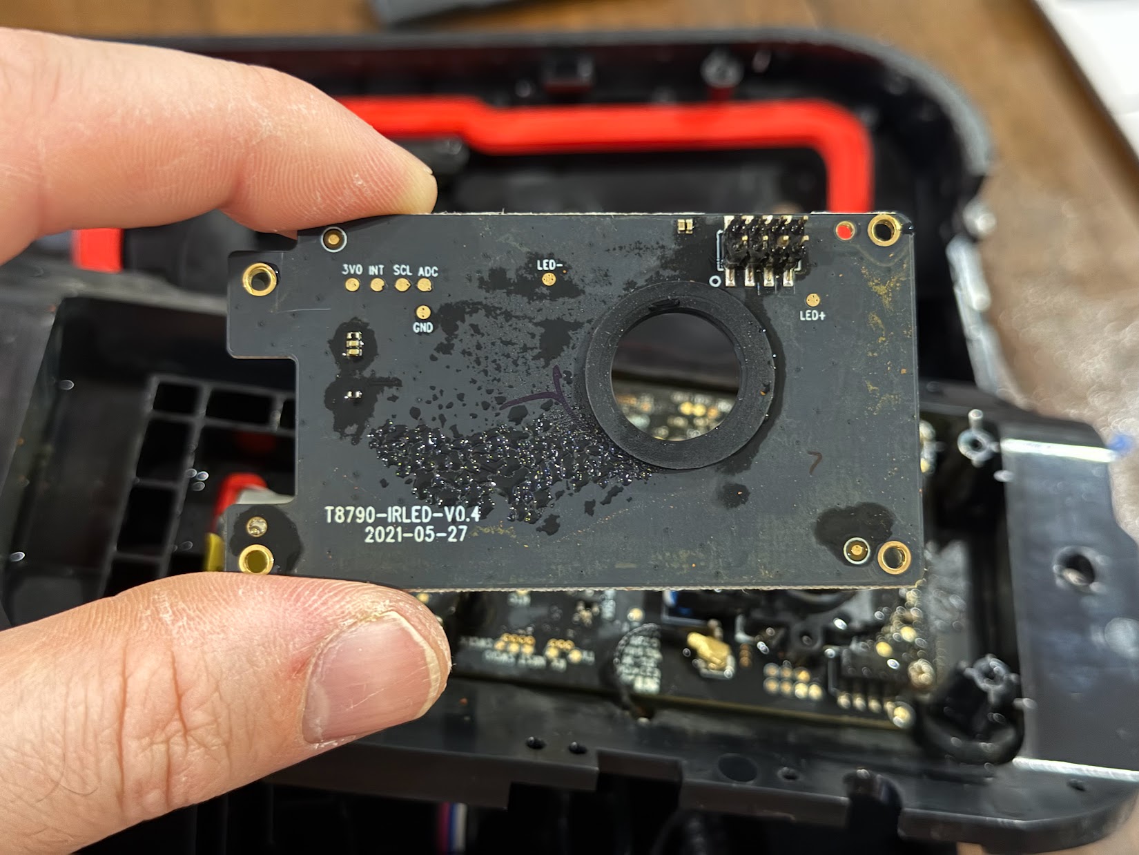
Bottom of the IR Board, part number T8790-IRLED-V0.4 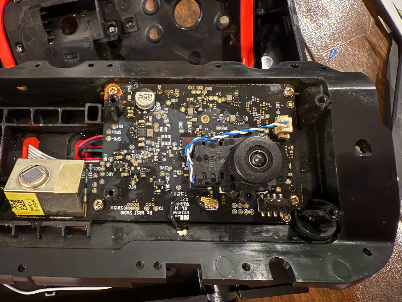
Next picture is a cropped and rotated version 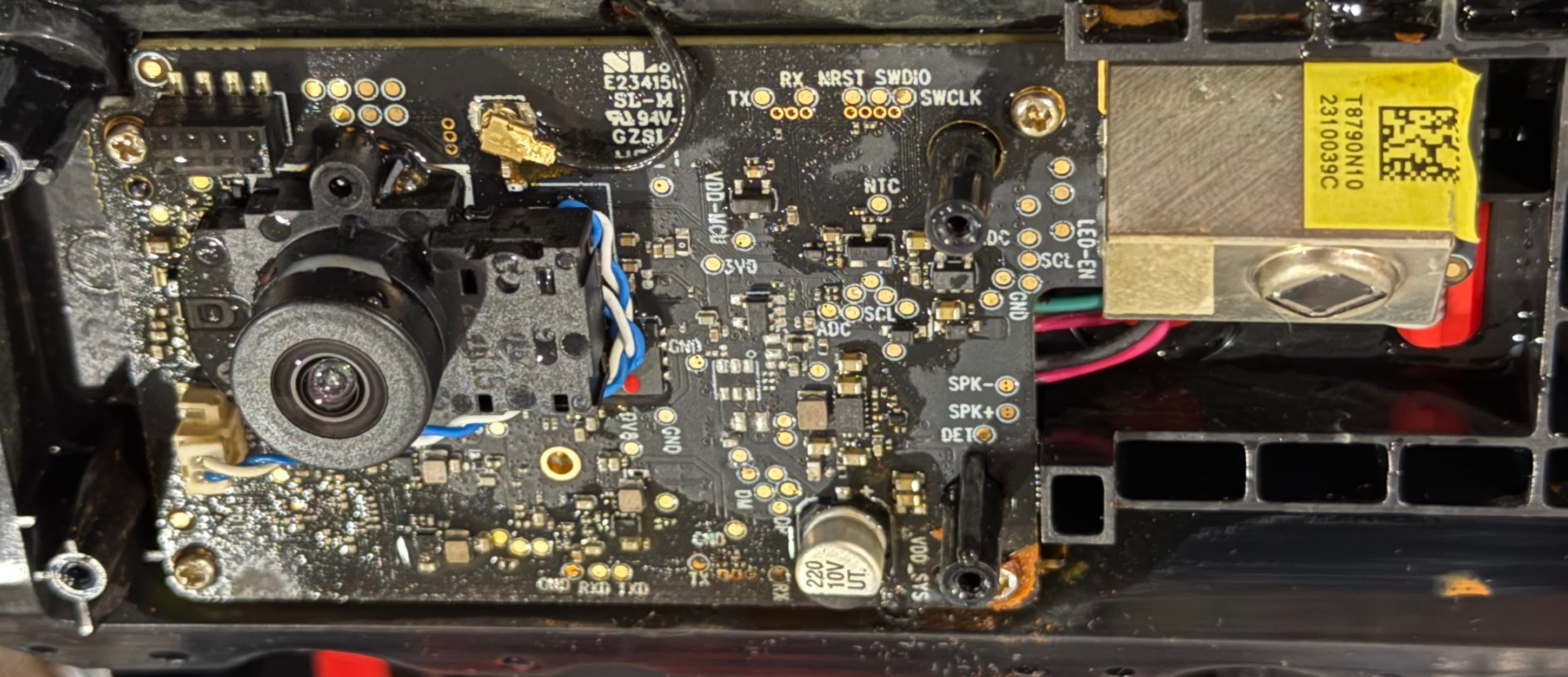
There’s a lot going on with the Brain Board. Some might say it’s overly complex for the task at hand, but that’s just their opinion.
Button Board Assembly Tear-down
The button board is held in by 8 screws. It has a single cable entry – an 8 conductor ribbon cable with one RED wire. The hole is well potted. 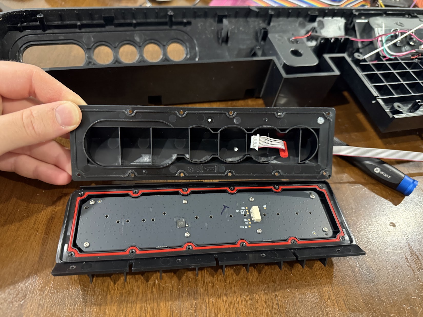
When an additional 12 screws are removed, the button board can be opened slightly – enough to remove the ribbon cable from the board. The button board looks clean! 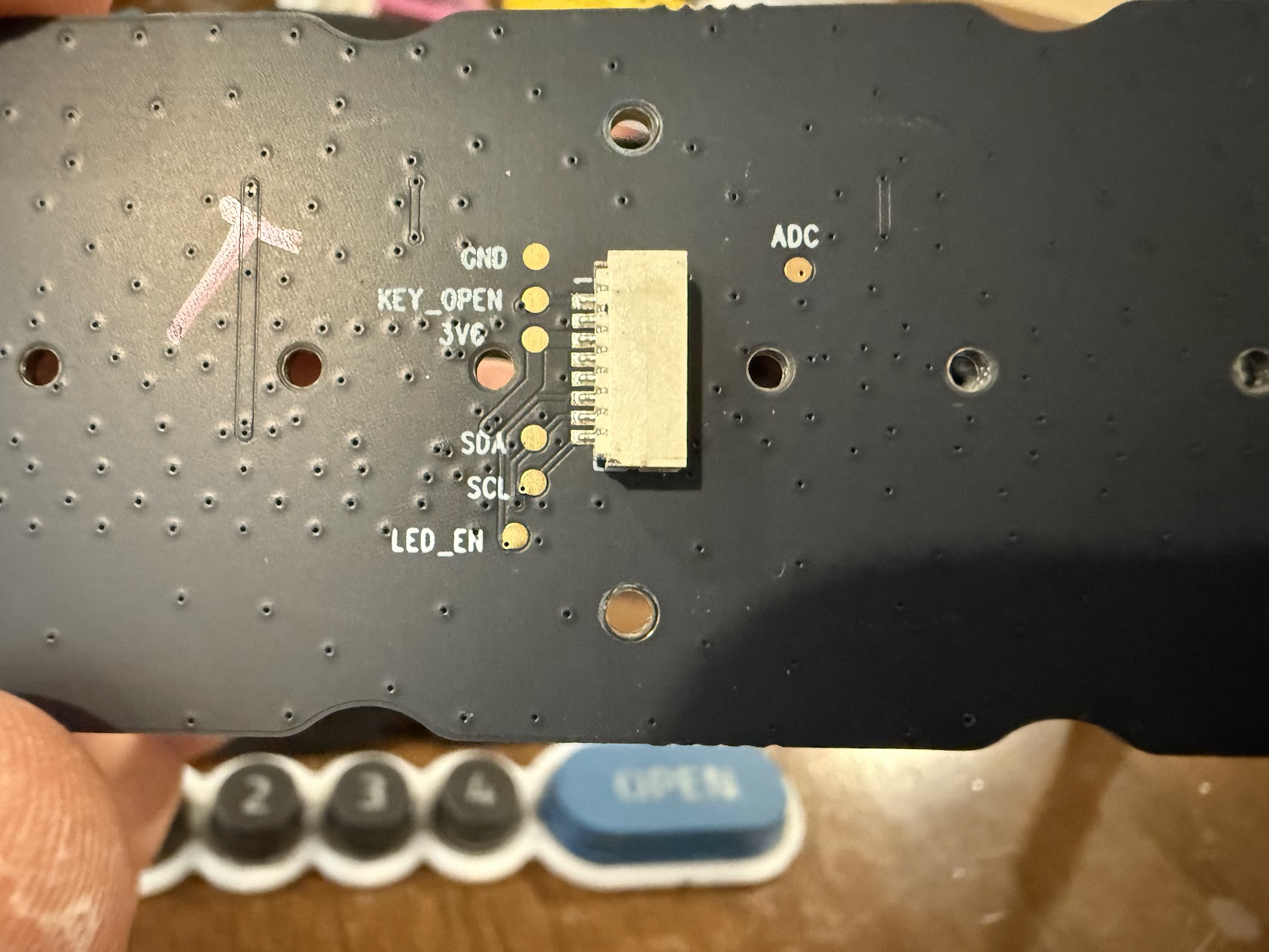
Button Board Back Connector. It appears the board communicates over a serial bus back to the brain board. 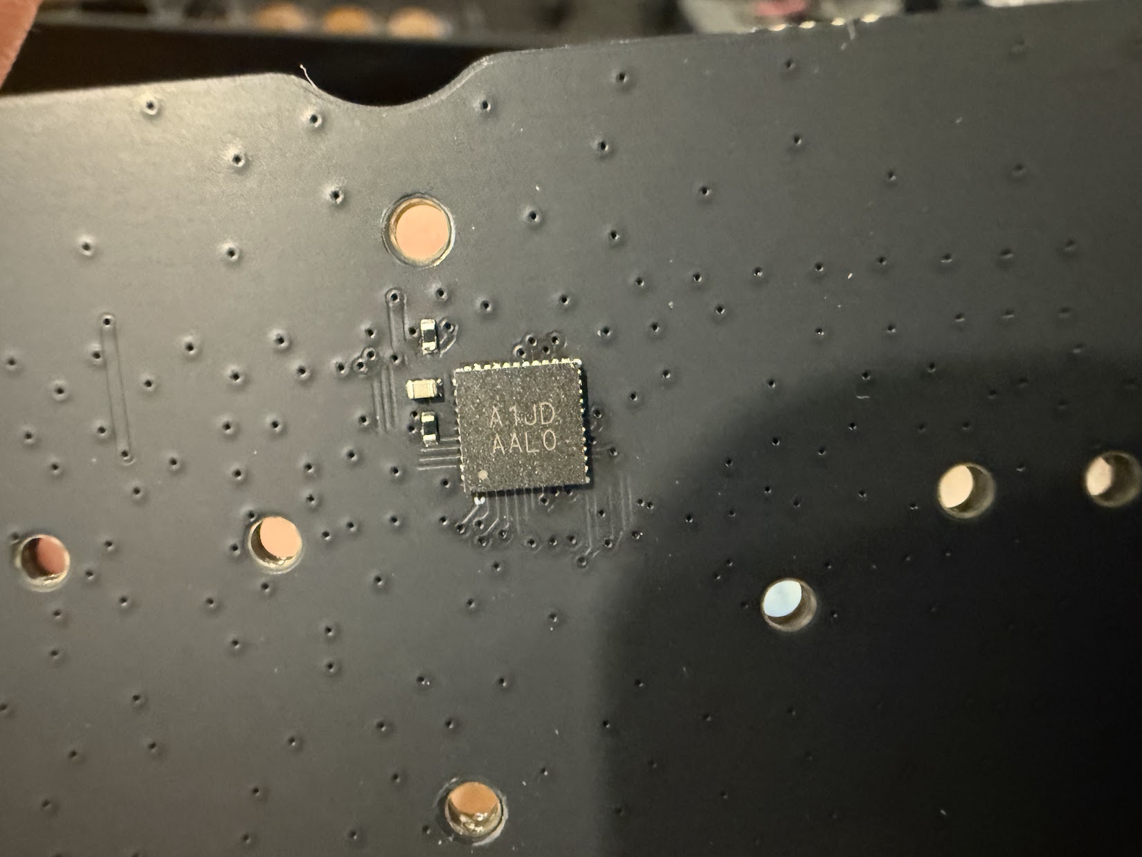
My guess is this chip registers the button presses and powers the LEDs, but I wasn’t able to find it online. 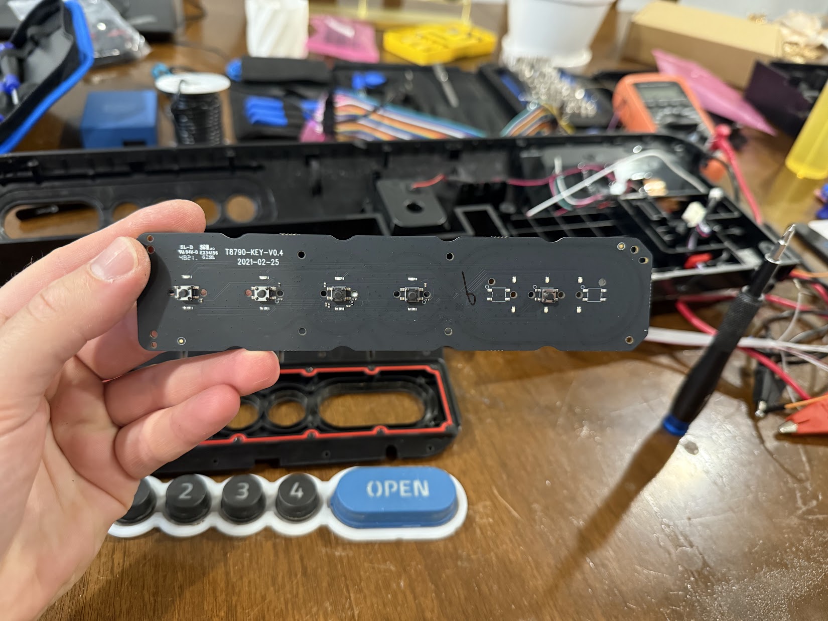
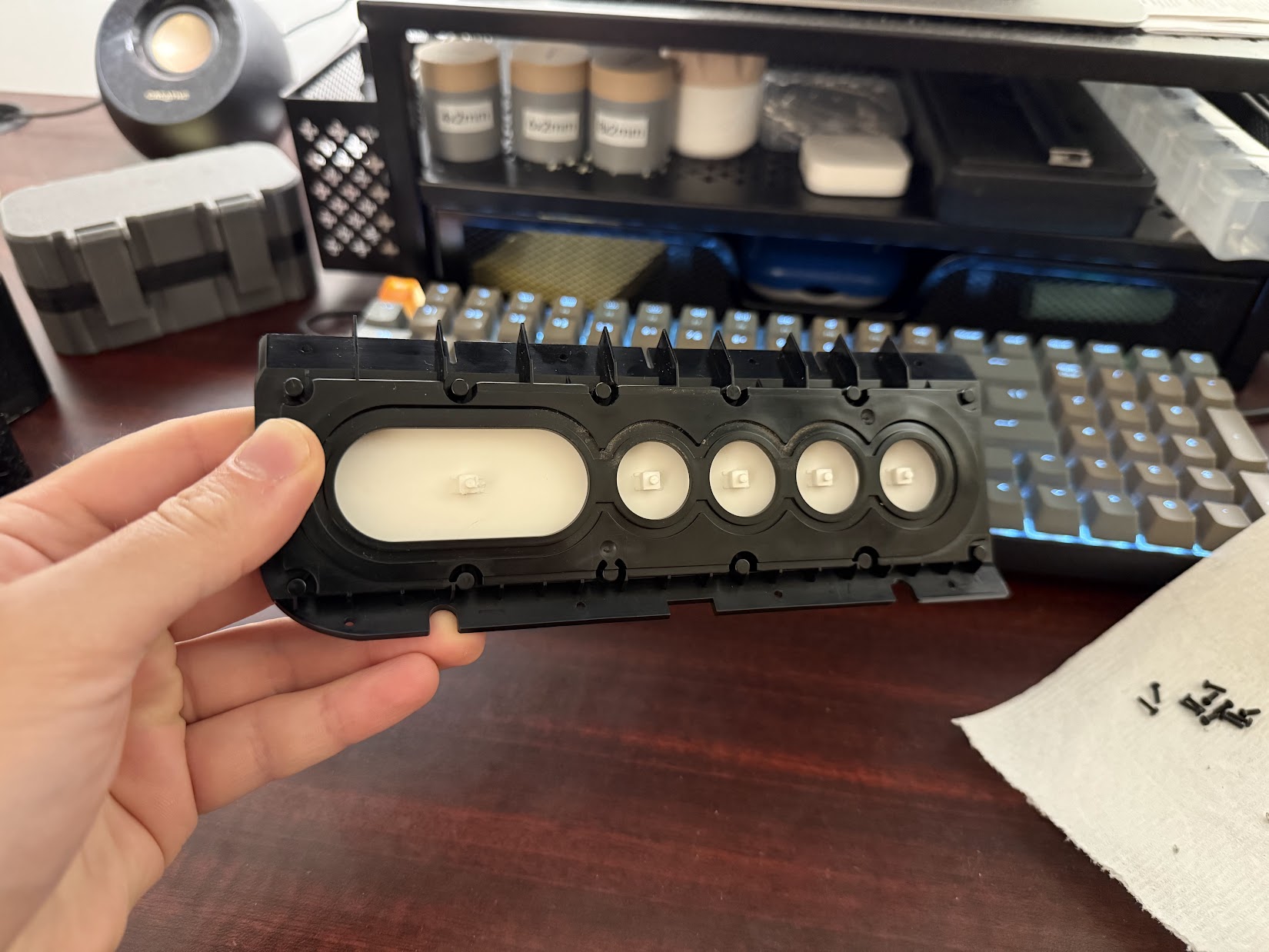
The front of the button board has five switches and LEDs for the backlights. 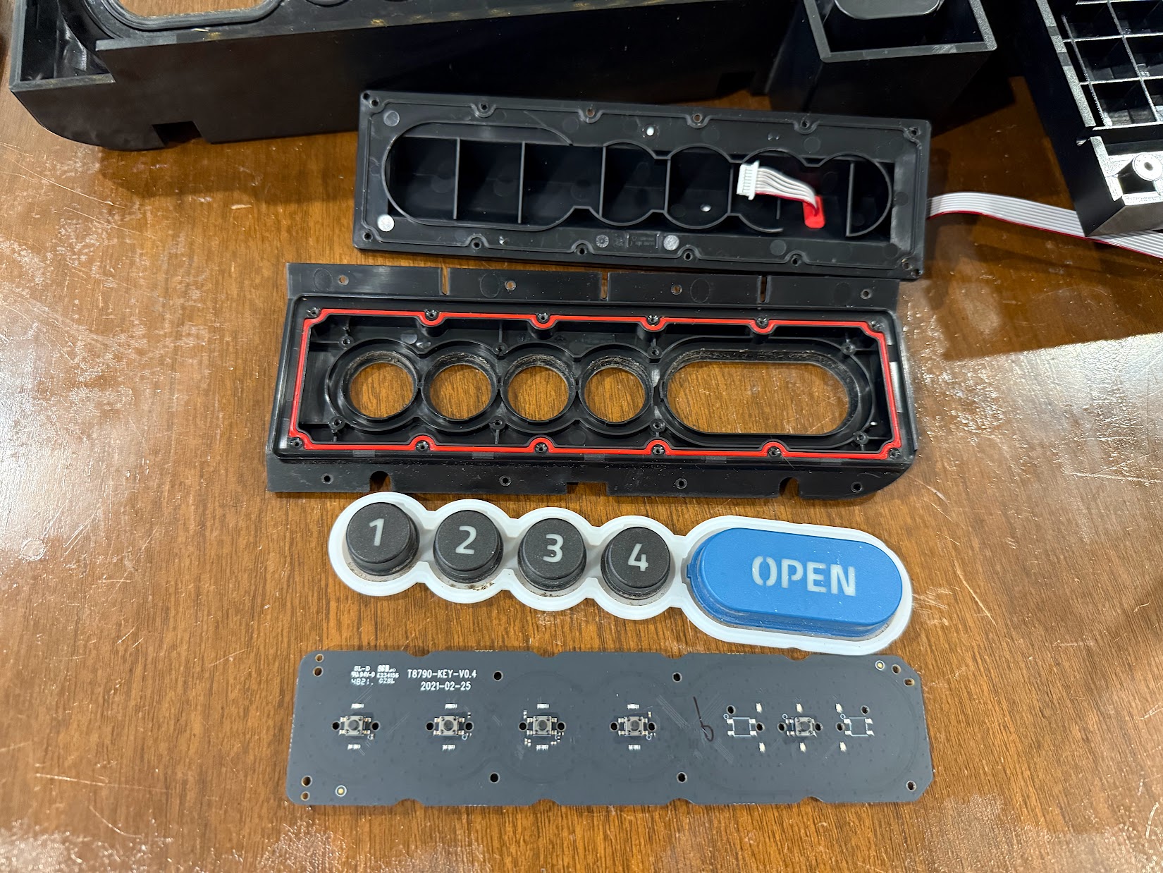
Button Board Assembly Parts T8790-KEY-V0.4 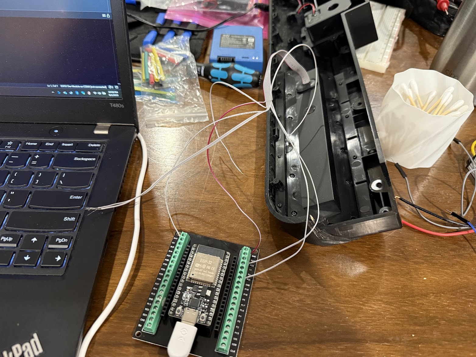
I attempted to connect to the serial bus using an ESP32, but wasn’t able to get anything useful.
Reverse Engineering Attempt
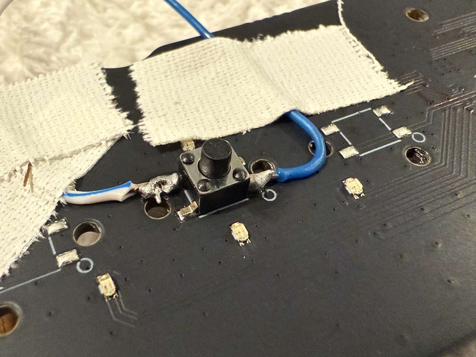
After taking the button board apart, I was hopeful that I would be able to use the existing hardware somehow. Either over the serial bus, or directly from the tactile buttons themselves. My first attempt trying to decode the serial bus using an ESP32 failed, so I decided to try and brute force the solution by soldering wires directly to the switches. Unfortunately, that didn’t work well either and I would need to pivot. But for now, here’s my awful soldering attempt:
Button Board Solder Attempt
Button Board Blue Solder Attempt 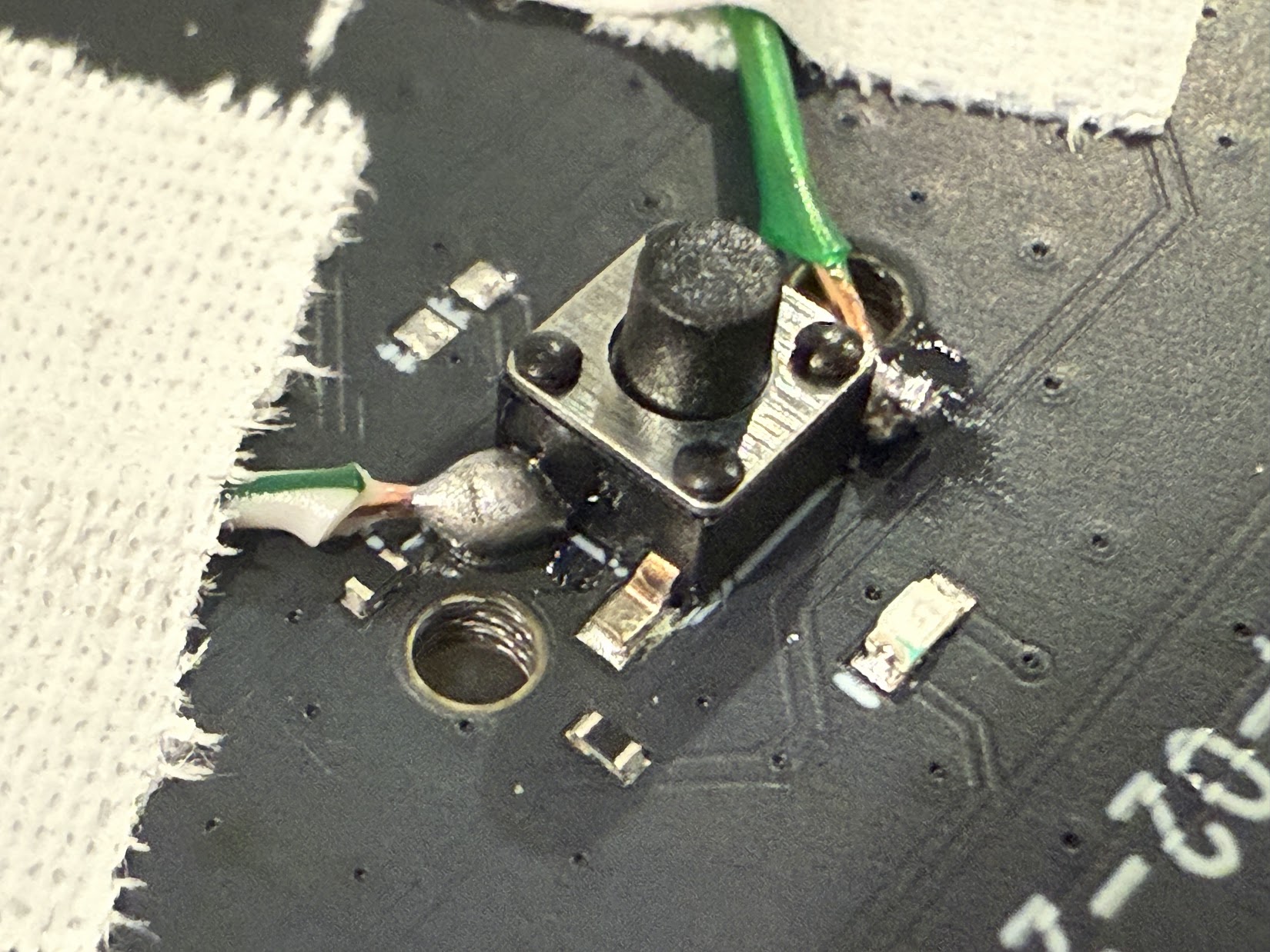
Button Board Green Solder Attempt 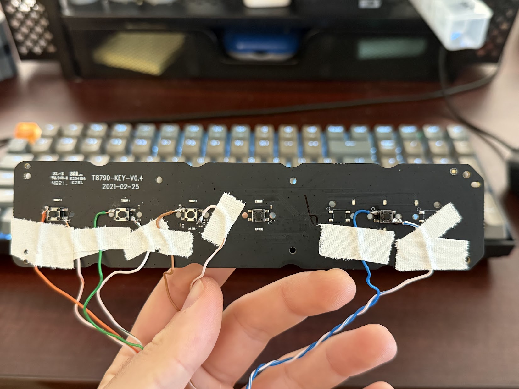
Button Board Solder Attempt 
Button Board Solder Attempt 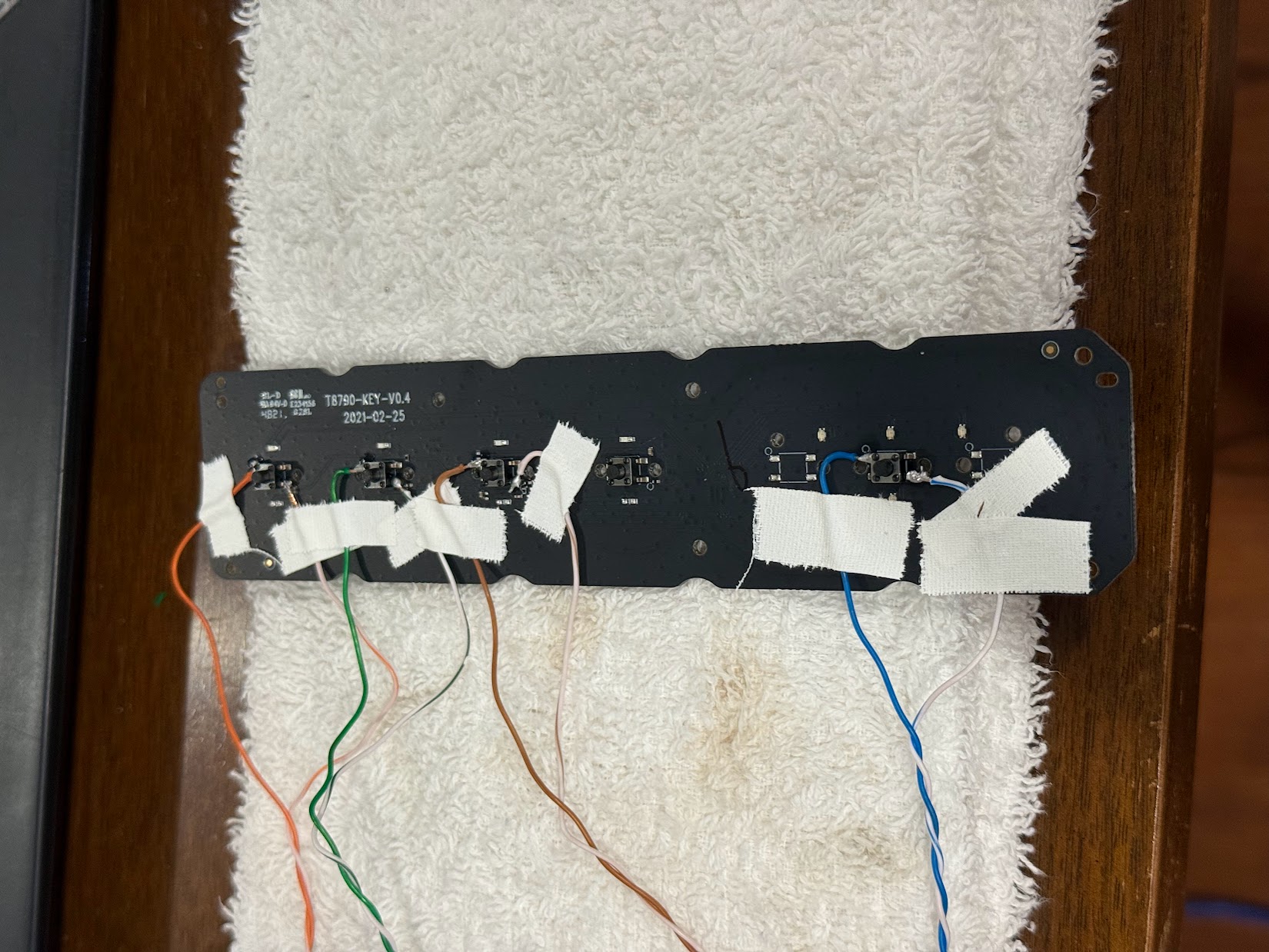
Button Board Solder Attempt 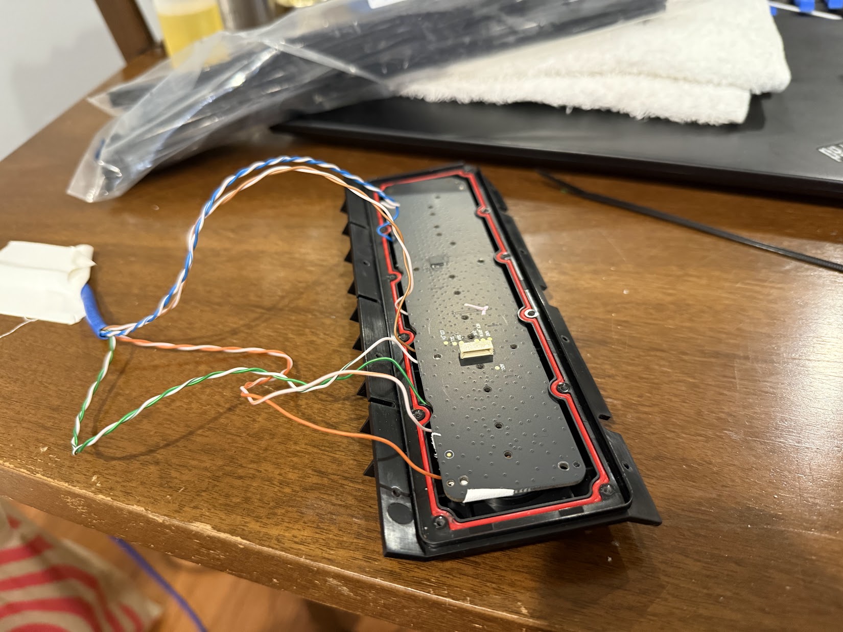
Carefully reinstalling Button Board with soldered wires 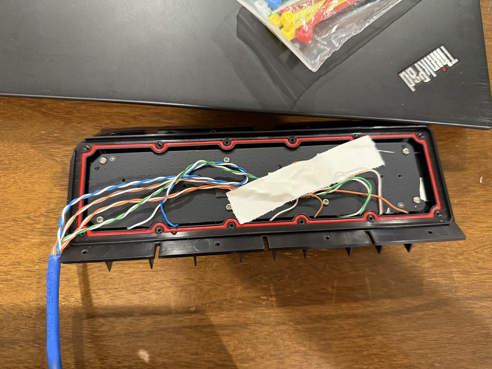
Added a bit of service loop and taped it down 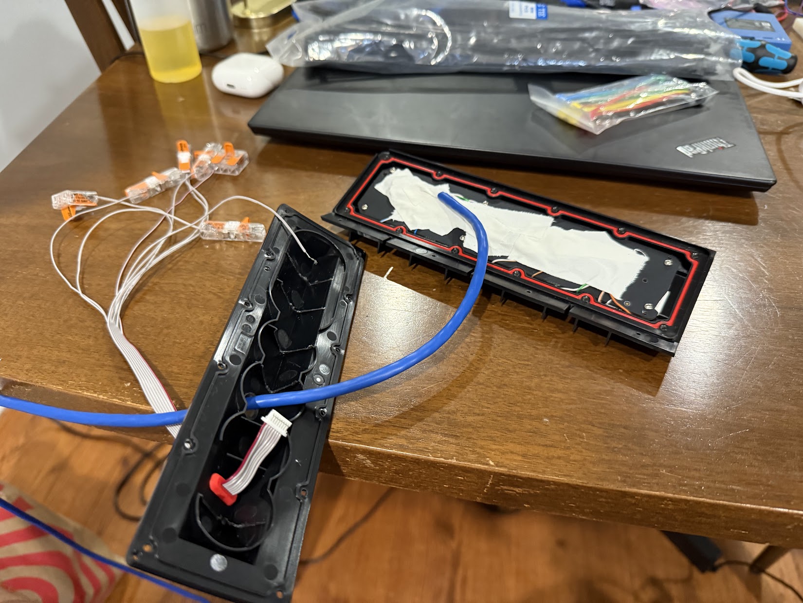
Fully taped remaining wires. Drilled a hole for the cable in the Button Board Case 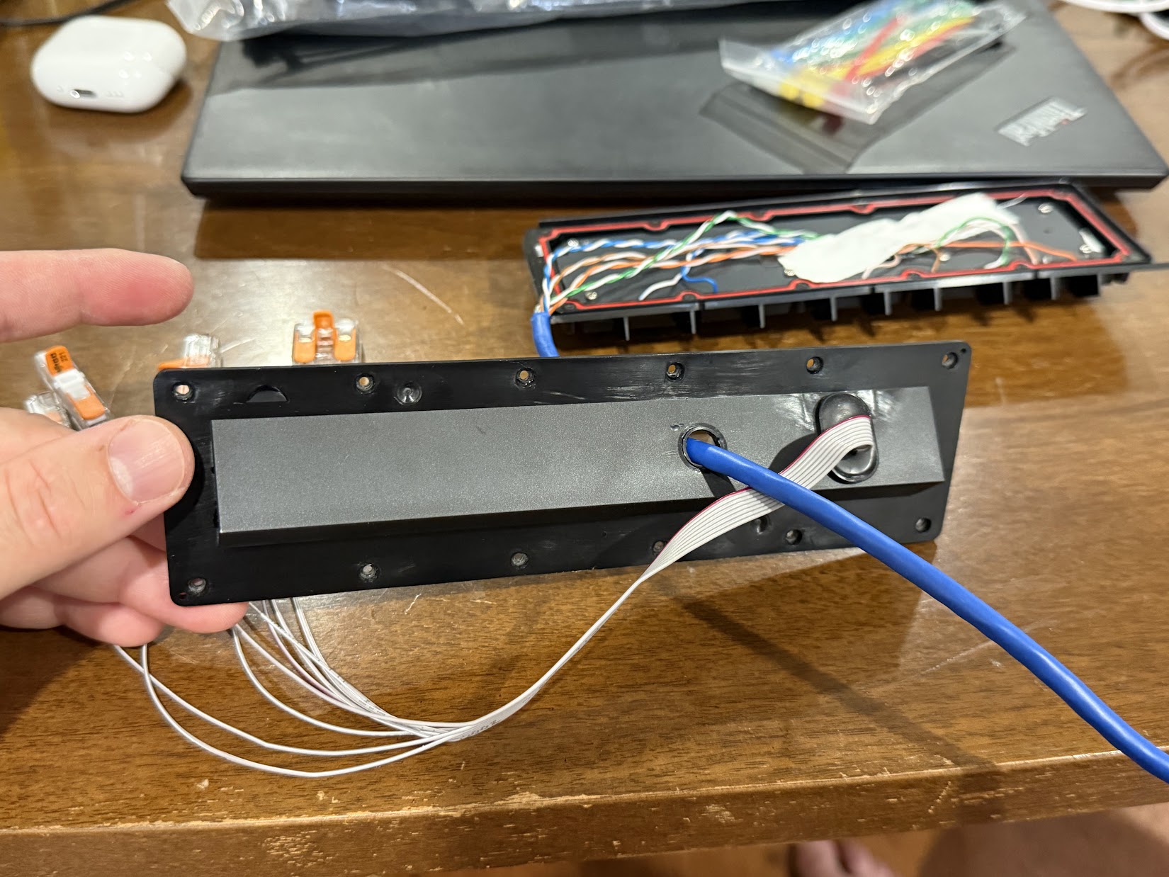
Fully taped remaining wires. Drilled a hole for the cable in the Button Board Case 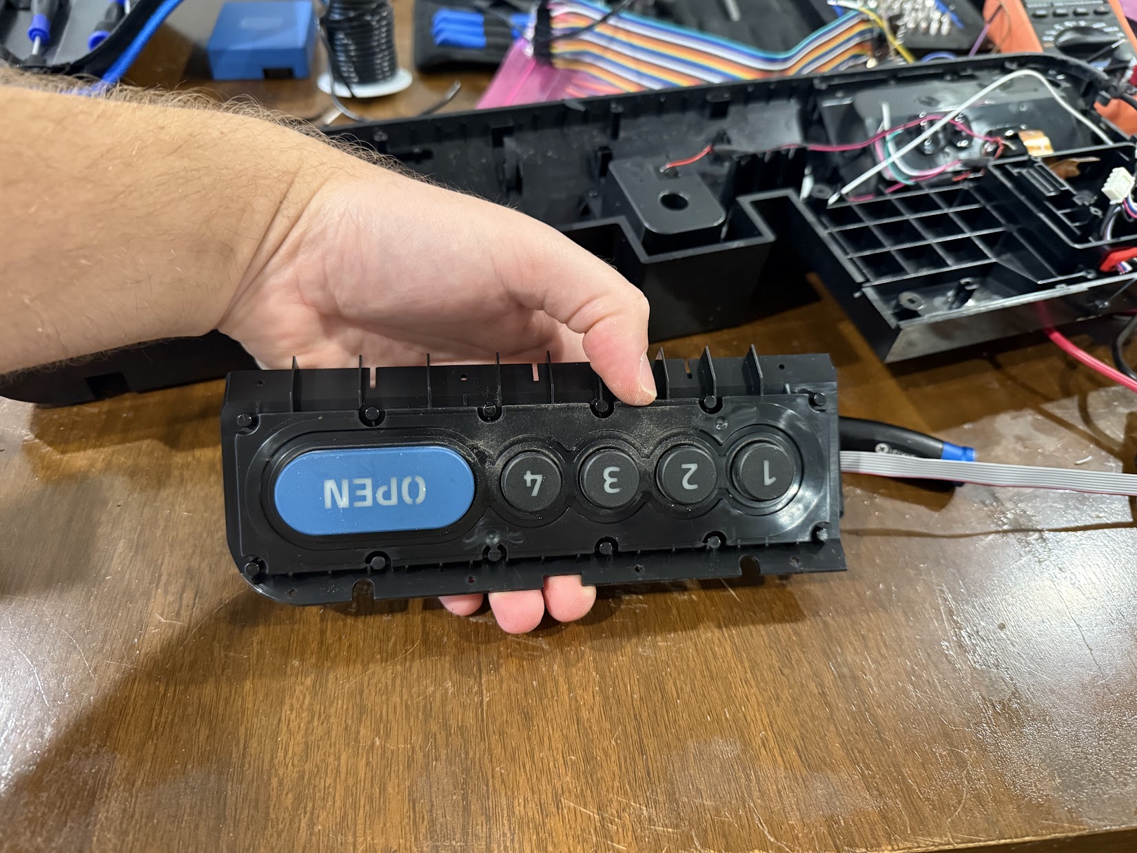
Button Board solder job all closed up 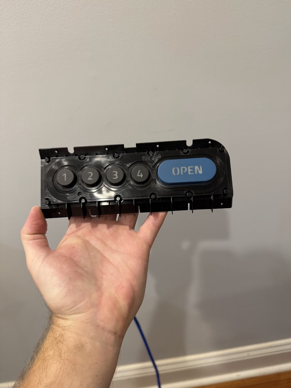
Button Board solder job all closed up 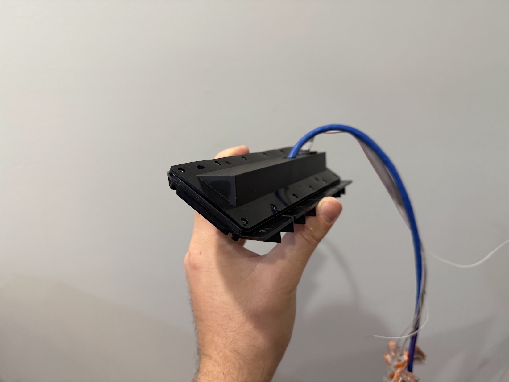
Button Board solder job all closed up 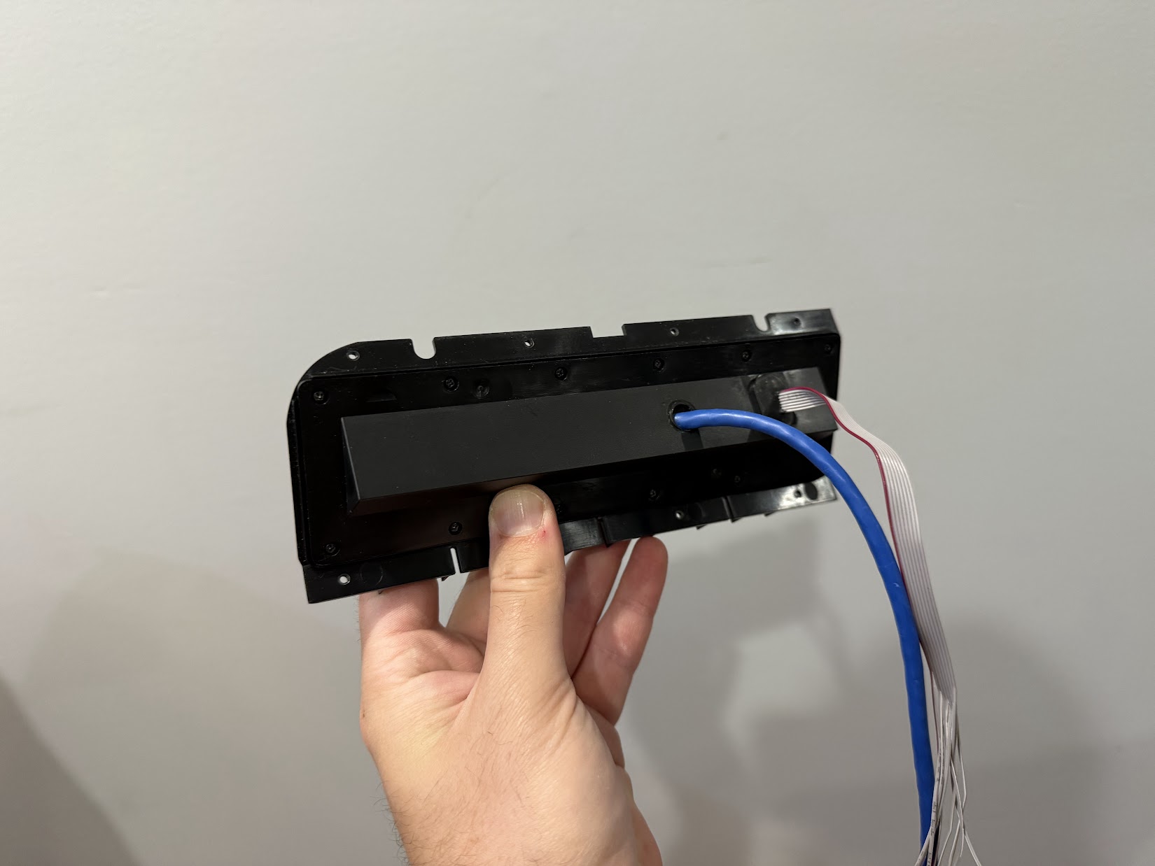
Button Board solder job all closed up
The solder job sort of worked, but not in the way I had hoped. It turns out I had made a small oversight when testing the bare PCB on the bench. I measured across each tactile switch while I pressed it, and I was able to see the switch leads closing. However, what I did not realize at the time is that ALL of the buttons shorted when ANY button was pressed. Or at least it produced low enough resistance to cause my multi-meter to beep, and wouldn’t have worked the way I intended. But, I am persistent, so I started measuring the resistance between pairs of wires as I pressed each button and I was able to find a pair where I could differentiate which button was being pressed by the changing resistance (GRN to BLU). Even better, I thought! It’s so simple, it’s perfect! The hand written notes from that effort below:
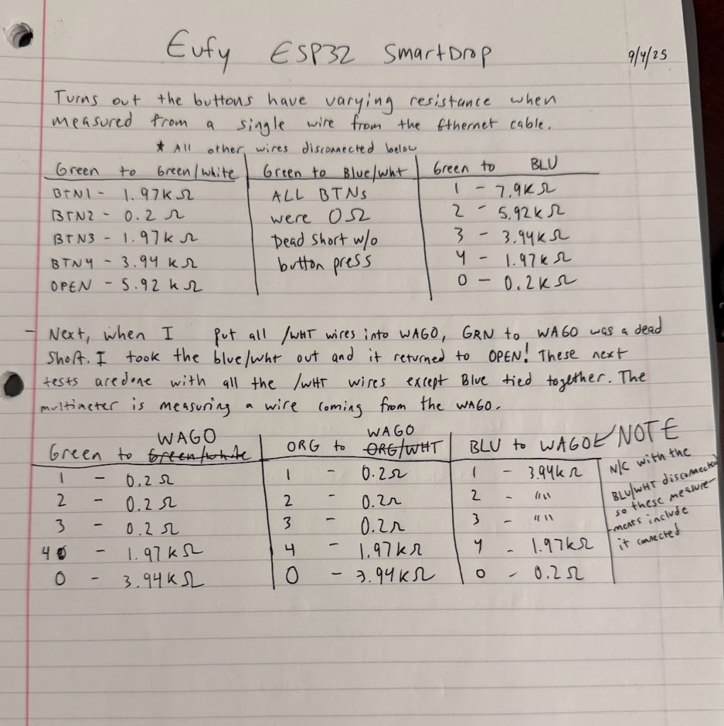
I was so excited to have found this solution. It was even better than my original idea and only used two wires! This resistance matrix solution worked for a while on the bench, but unfortunately, trying to solder leads onto the SMD components with a soldering iron did not prove to be very reliable (shocker, I know). The joints were all cold and some even fell off as I tried to tape them down and close everything up. After only a couple days, the readings on my test setup had become so inconsistent that they weren’t usable at all. The voltage wasn’t returning to the expected values and sometimes buttons weren’t registering at all. It was around this time that I decided to start again from scratch. I was going to design my own custom PCB instead.
Custom PCB Attempt
The first step I took was to model the board as closely as possible. I used OnShape and my trusty calipers to model all the dimensions of the board. Then, I used my Bambu P1S to print it out and test the fit. After a couple tries, I had something extremely close and decided to call it good enough.
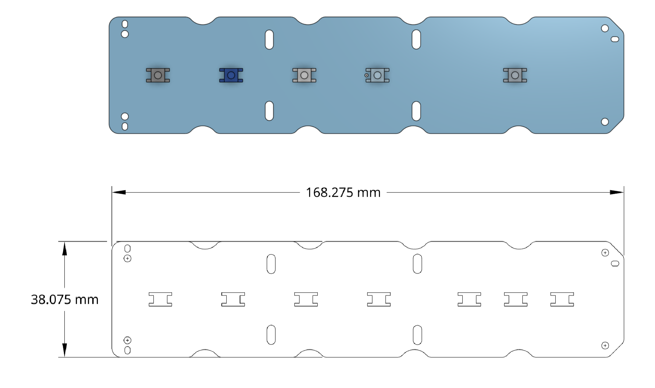
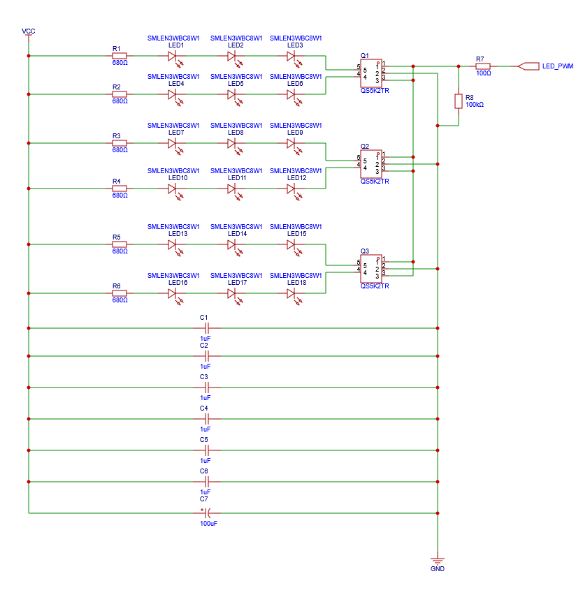
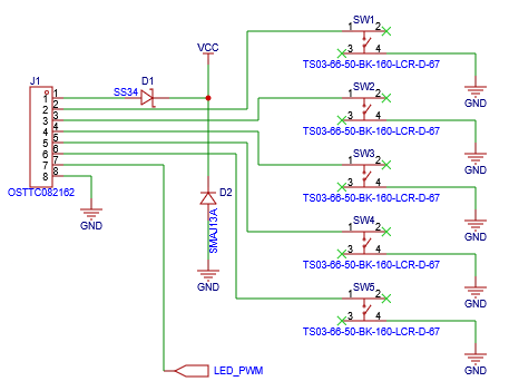
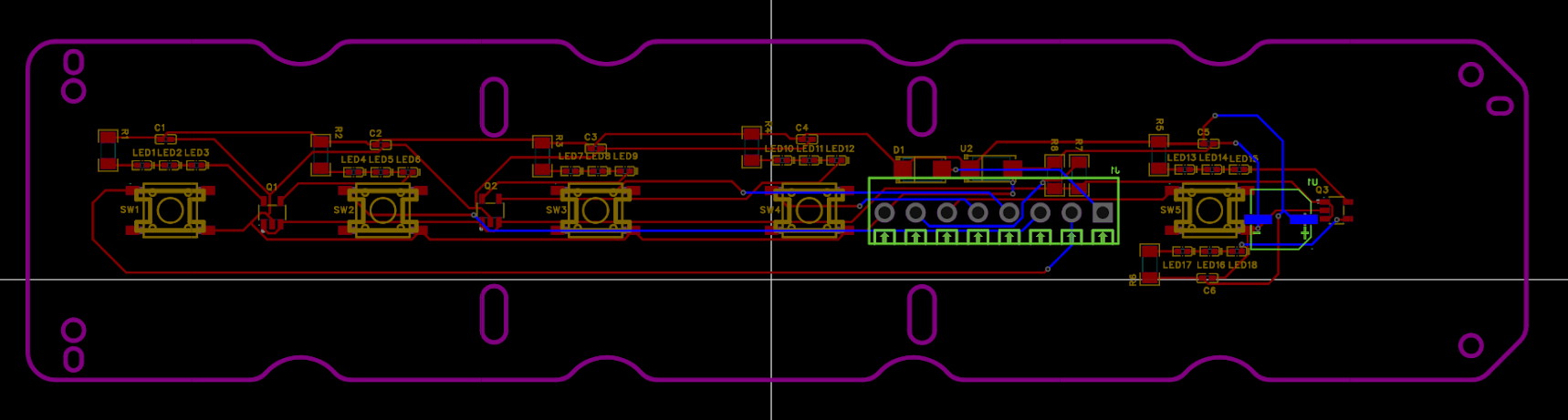
In OnShape, I used the 3D model to create a drawing which contained the outline of the board and the mounting hole cutouts. I imported the .dwg file into EasyEDA (not a sponsor) and moved it to the outline layer. From there, I searched though the standard parts catalogue of JLCPCB (also not a sponsor) to find switches that were approximately the same footprint as the originals. I also found a relatively low profile terminal block and a handful of other components intended to work as a backlight for each switch. I won’t spend much time writing about this process, but the schematic and PCB layout are shown below:
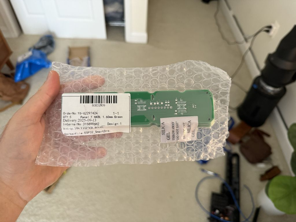
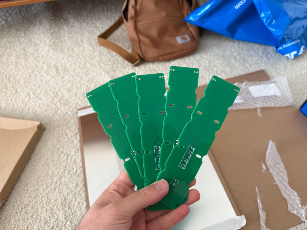
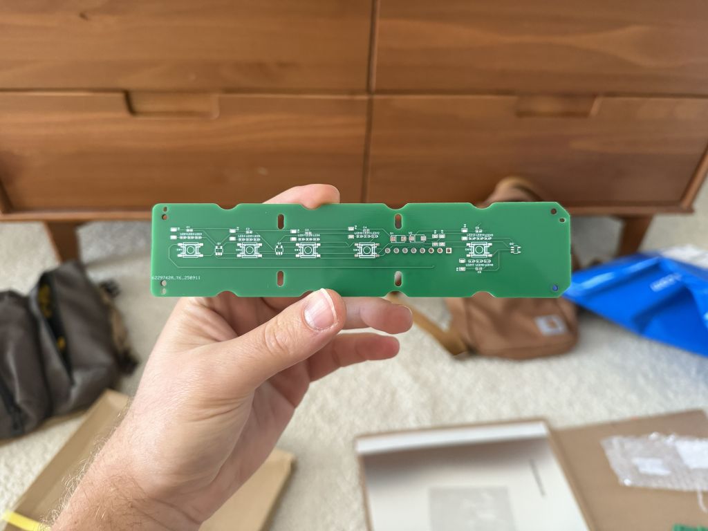
They took a while to arrive (coming from halfway across the world), but the boards looked really good!
First-Ever SMD Soldering
I had to purchase some flux, paste, and a heat gun from Amazon to attempt my first SMD soldering! I was smart enough to purchase the custom solder mask from JLCPCB, which made the work of spreading the solder onto the board quite easy. Then, it took about half an hour with some tweezers and a very steady hand to place all of the components onto the board. Finally, I set up the heat gun and slowly started flowing different components. It was incredibly satisfying watching the components get sucked into place as the solder started to melt. I can honestly say I prefer using paste and a heat gun over a soldering iron and wire any day!
After soldering everything in place, I tested on the bench with the ESP32 and everything worked except the LED circuit. I didn’t have the patience to redesign the board and wait for a new batch to ship, so I went without the backlight.
I used an Ethernet cable to connect the ESP32 to the button board, just as I originally planned. With the LED backlight nonfunctional, there are two spare wires that would have been the LED_PWM signal, and the 12v line. The other 6 wires are SW1-SW4, the OPEN switch, and a signal GND as a reference for each of the switches.
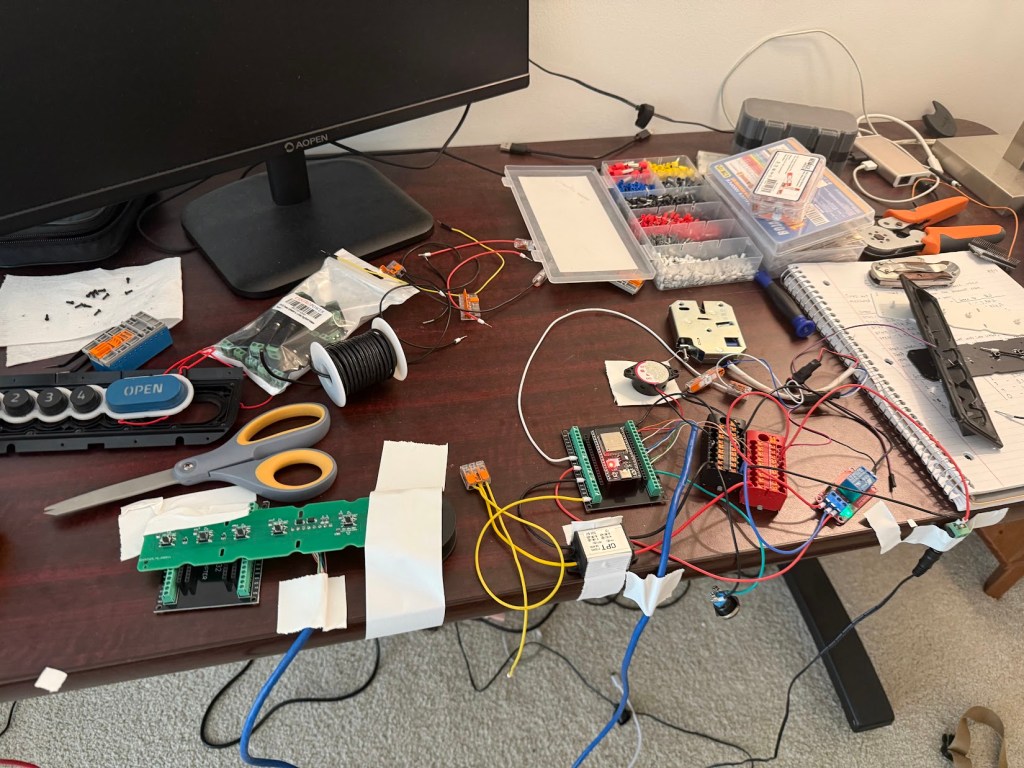
With the new button board, latch assembly, ESP32, terminal blocks, buzzer, and relay board wired up, the next step was to create the ESP32 code. To accomplish this, I created a design document that I fed into ChatGPT. It contained an overview of the project, guidelines for behavior, a detailed list of each input and output, credentials for WiFi and MQTT, and a list of configuration details. I’ve attached the latest design document below, which includes the hotspot functionality – when the device first boots, it will create a hotspot which the user can connect to and set the initial WiFi/MQTT configuration.
After about a week of massaging the code, I was able to create a working prototype. Everything went perfectly while on the bench, but problems quickly began when the Function Panel was reinstalled into the metal shell of the Eufy box. For whatever reason, every time the ESP32 would command solenoid, the ESP32 would restart. Sometimes, it would recover and reconnect to WiFi/MQTT, while other times it entered an unrecoverable state which persisted until a power cycle.
My first thought was that the solenoid was drawing too much current and it was causing the power to sag enough that the ESP32 turned off. However, the reboots persisted even after I added a resistor inline with the solenoid and measured with a multi-meter to verify rock solid voltage. I also attempted to make the latch pulse as short as possible, hoping that may help, but it didn’t fix the issue either.
My next thought was that the solenoid was causing a voltage spike on the negative leg when the solenoid was switched off, and that spike was somehow forcing the ESP32 to reboot. So I purchased a pack of 5A diodes from Amazon to test out that theory. Unfortunately, adding the fly-back diode also didn’t fix the problem. I tried adding a diode inline with the ESP32 relay board trigger output, hoping to prevent back-driving the ESP32 but no luck there, either.
Finally, I tried probing the circuit with a multi-meter between the ESP32 relay trigger output and the GND terminal block while activating the lid release solenoid, and magically the ESP32 didn’t reboot! It stayed fully connected to the WiFi and MQTT without even a hiccup. For whatever reason, measuring the circuit fixed the issue. So after some more trial and error, I found that adding a 100kohm resistor between the trigger output and GND fully fixed the reboot issue, no diodes necessary, though I did add a fly-back diode for the solenoid anyway, to help protect the relay board from voltage spikes.
Packaging + Mounting
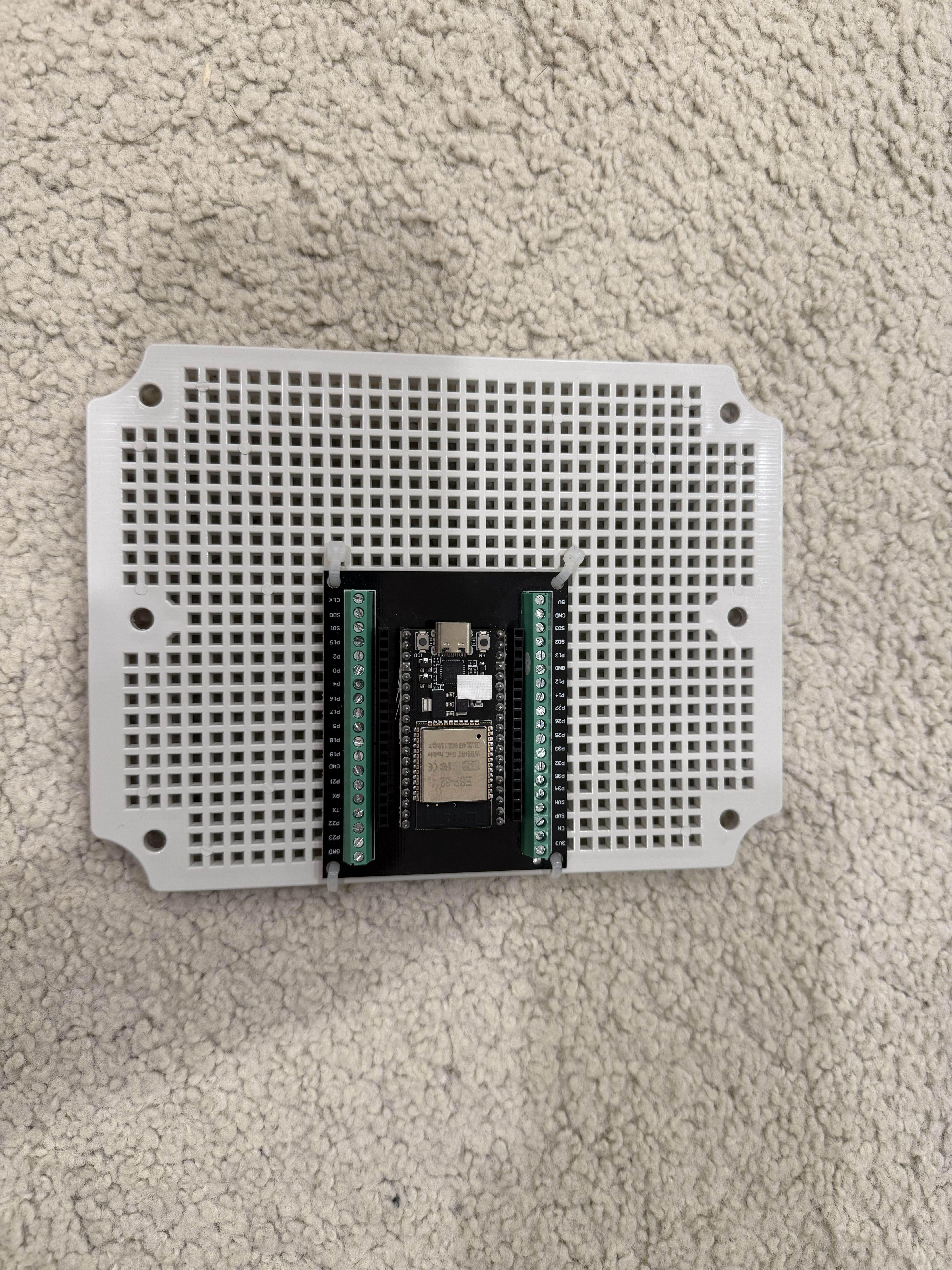
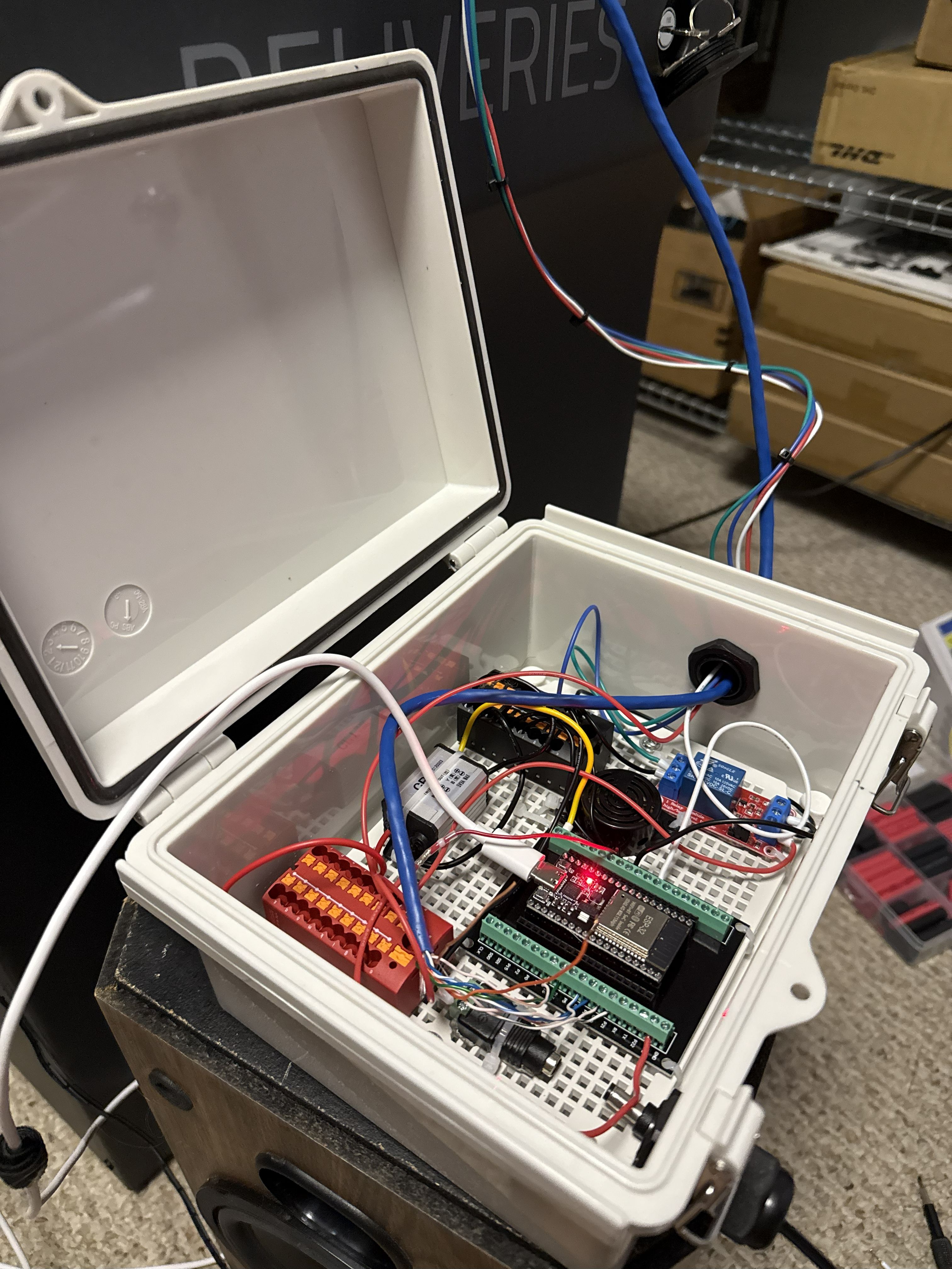
Now, I just needed to package everything up! I decided to use a waterproof ABS junction box from Amazon, and I’ve been pleasantly surprised at the quality. It’s got a nice seal, strong latches, an internal mounting plate, and it even comes with two cord grips.
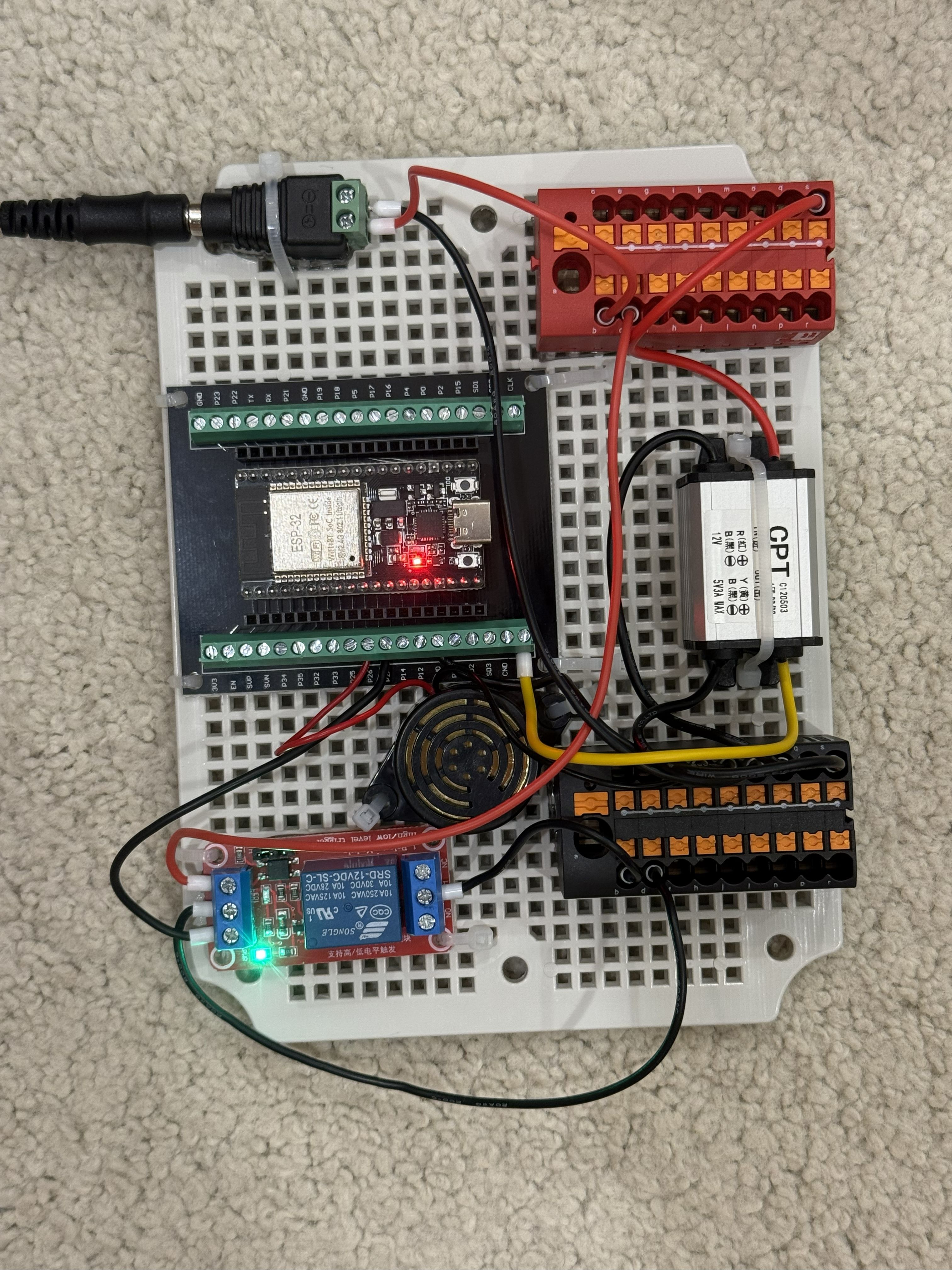
Component Choice: I opted to use terminal blocks from Phoenix Terminal, but any terminal block with enough positions would work. I bought some female DC Jacks with screw terminals for the 12V input, and used a 12V to 5V DC/DC converter to power the ESP32. I also purchased a continuous sound buzzer for button feedback. These are linked at the bottom of this post.
To mount each component, I placed a layer of “Alien Tape” underneath and secured it down to the box’s mounting plate with a couple zip-ties. The Alien Tape helps conform to uneven surfaces and absorbs some shock/vibration. My first attempt to mount the junction box inside the SmartDrop failed miserably. I used the same Alien Tape and it fell off within a day, so I decided to use a couple screws instead. Now, it’s definitely not coming off unless I want it to!

Conclusion
With the electronics safely inside their junction box, and the junction box safely mounted inside the SmartDrop, it was finally ready to be put outside! The box is a little bit tall, so you can see it slightly when leaning over the SmartDrop, but it doesn’t get in the way of packages. There was a small hiccup after a few days, but I refactored some of the code and it’s been working reliably ever since!
So there you have it. After a full tear-down, a failed attempt at salvaging the original button board, a custom PCB design, and some frustrating troubleshooting, the SmartDrop is officially revived.
What was once a discontinued, unsupported piece of tech is now a fully local, open-source, reliable smart device running on an ESP32 and integrated directly into Home Assistant via MQTT. It’s faster, more stable, and 100% under my control – no cloud servers required. It was definitely a challenging build, but I’m thrilled with the final result.
I hope this detailed write-up and the project files below help anyone else out there looking to give their own Eufy SmartDrop a new lease on life. Happy hacking!
APPENDIX
Download the code, 3D model, schematic, PCB outline, and more here!
Home Assistant Cards
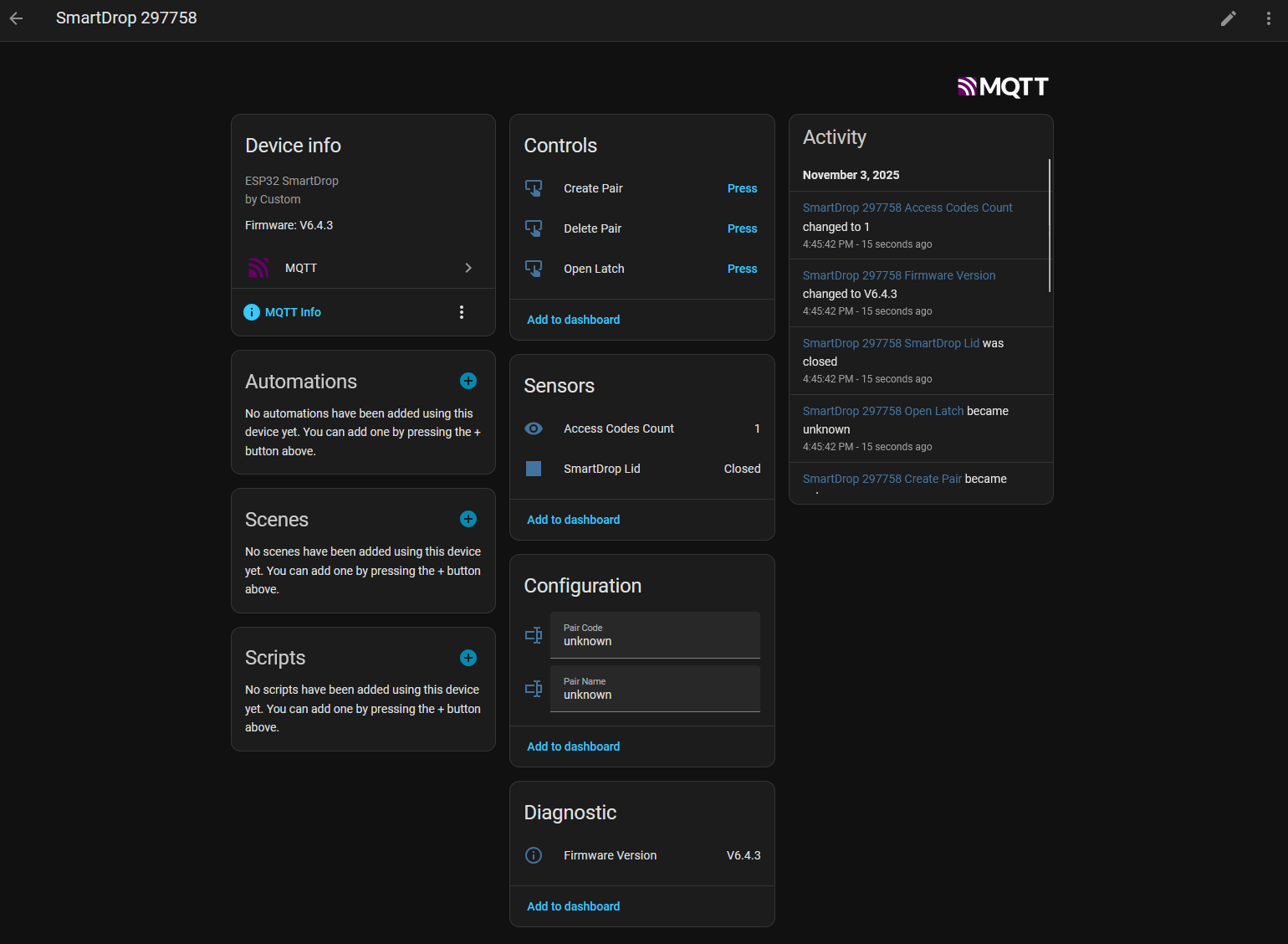
If you already run Home Assistant with MQTT, this project should be an absolute breeze to integrate. When you first run the ESP32_SmartDrop code, it will create a hotspot with a configuration page to enter your WiFi and MQTT credentials. When it connects, it will auto-configure the entities within home assistant, including:
- Text entry boxes to enter a new code pair
- Buttons to create and delete code pairs
- A manual “open latch” button
- A sensor for the lid status
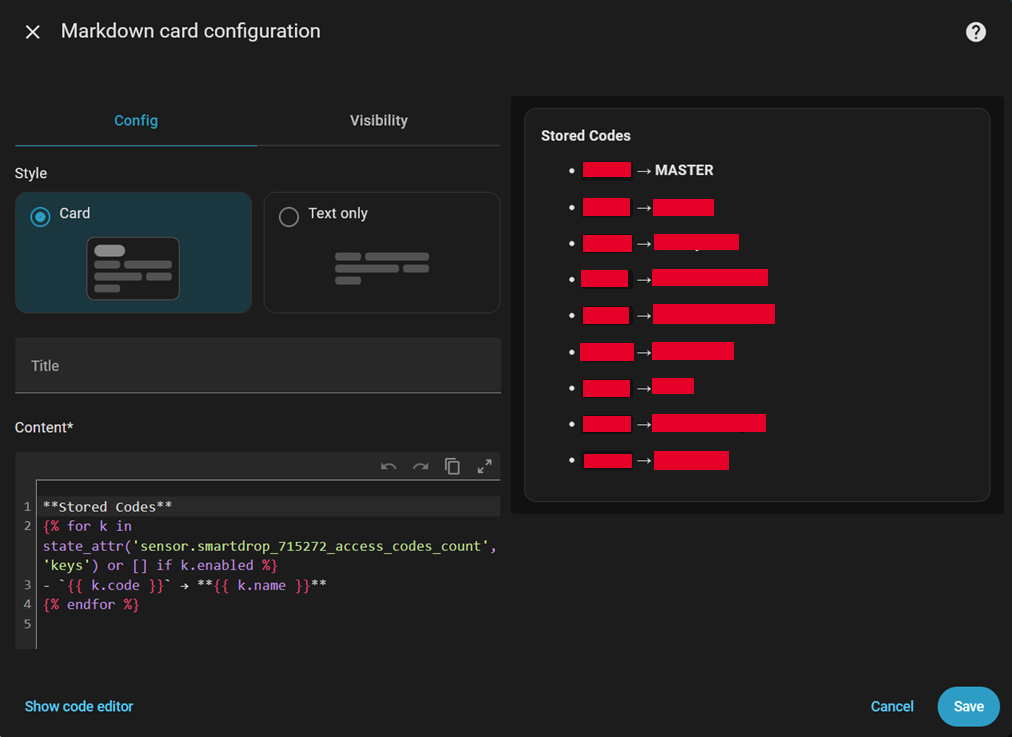
- A sensor with the number of stored passwords (plaintext passwords can be found in the “Attributes” of this entity)
- A sensor with the firmware version
This is what it should look like if it connects/configures successfully – I didn’t manually configure any of this, it’s automatic!
Bill of Materials (other than PCB)
Here are all the parts I purchased for this build – no tracking or affiliate links, these are just the actual parts I used:
- ESP32 + Breakout Board with Screw Terminals
- Schottky Flyback Diode for Relay Suppression
- Plastic Weatherproof Enclosure w Cord Grips
- SMD Soldering Paste
- SMD Soldering Flux
- Hot Air Rework Station
- External Relay Board
- Electronic Buzzer/Beeper
- 12V to 5V DC/DC Converter
- 12V Female Jack with Screw Terminals
